
User's Manual
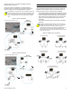
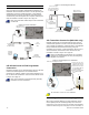
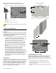
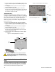
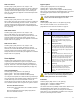
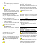
Table Of Contents
- Introduction
- About Magellan and this Manual
- Conventions
- Specifications
- Quick Setup
- Installation
- AC Power
- DC Power
- Backup Battery Pack
- Auxiliary Output
- Telephone Line Connections
- Programmable Outputs (PGMs)
- Hardwire Zone Connections
- WinLoad Connection
- UIP-256 Universal In-Field Programmer Connection
- X10 Transmitter Connection (MG-6160 only)
- Connecting a Paradox Memory Key (PMC-3)
- Location and Mounting
- Connecting the Radio Antenna (MG-6160 only)
- Programming Methods
- WinLoad Installer Upload/Download Software
- Programming Using the Built-in Keypad
- Programming Using a Paradox Memory Key
- User Codes
- User Code Length
- Installer Code
- Maintenance Code
- System Master Code
- Duress Code
- Zone Programming
- Zone Programming Overview
- Zone Definitions
- Zone Options
- Zones 31 and 32 Become Hardwire Zones
- EOL (End-Of-Line) Zones
- Assigning Wireless Zone Transmitters
- Assigning Wireless Doorbells to the Console
- Deleting Assigned Wireless Transmitters
- Viewing Wireless Transmitter Signal Strength
- Assigning Remote Controls
- Programming the Remote Control’s Buttons
- Assigning Wireless Keypads
- Assigning Wireless Repeaters
- Wireless Repeater Options
- Arming and Disarming
- Regular Arming Switches to Stay Arming
- Regular Arming Switches to Force Arming
- Stay Arming Switches to Force Arming
- Timed Auto-Arming
- No Movement Auto-Arming
- Auto-Arming Options
- One-Touch Arming
- Exit Delay
- Bell Squawk on Arm/Disarm with Remote Control
- No Exit Delay when Arming with Remote Control
- Exit Delay Termination
- Follow Zone Switches to Entry Delay 2
- Closing Delinquency Timer
- Stay Arm Siren Delay
- Alarm Options
- Bell Cut-off Timer
- Wireless Transmitter Supervision Options
- Check-in Supervision Options
- Tamper Recognition Options
- Wireless PGM Supervision Options
- Wireless Keypad Supervision Options
- Wireless Repeater Supervision Options
- Wireless PGM Console Supervision Options (Follow Alarm/Follow Bell)
- Backup Alarm Reporting Option
- Panic Alarms
- Reporting and Dialer Settings
- Report Codes
- Console Telephone Numbers
- Console Account Number
- Reporting Formats
- Event Call Direction
- Delay Between Dialing Attempts
- Alternate Dial Option
- Force Dial Option
- Dialing Method
- Pulse Ratio
- Switch to Pulse Dialing on 5th Attempt
- Telephone Line Monitoring (TLM)
- Recent Close Delay
- Auto-Test Report
- Power Failure Report Delay
- Disarm Reporting Options
- Zone Restore Report Options
- RF Jamming Supervision
- Programmable Outputs
- Assigning PGMs
- Setting PGM Function
- Onboard PGM Activation Event
- Onboard PGM Deactivation Event
- Onboard PGM Delay
- PGM Normal State (Onboard Only)
- PGM X10 Option (MG-6160 Only / Onboard Only)
- Wireless PGM Activation Event
- Wireless PGM Deactivation Event
- Wireless PGM Delay
- System Settings
- Software Reset
- Installer Lock
- Console Tamper Supervision
- Console Audible Trouble Warning
- FM Tuner Option (MG-6160 only)
- Daylight Savings Time
- AC Power Failure Warning
- The Trouble Display
- WinLoad Software Settings
- Panel Answer Options
- Panel Identifier
- PC Password
- PC Telephone Number
- Call Back Feature
- Appendix 1: Automatic Report Code List
- Appendix 2: Ademco Contact ID Report Code List
- Index

Paradox Magellan Systems 9
Normally Closed (N.C.) as detailed in PGM Normal State
(Onboard Only) on page 35.
If the current draw on the PGMs is to exceed 100mA, we
recommend using an external relay as shown in Method 2 in
Figure 7 on page 9. For connecting PGM2, see Figure 8.
Using Method 2, connect the device to the output terminal of the
external relay that matches the normal state of Magellan’s PGM
output. For example, if PGM1’s normal state is Normally Open
(N.O.), connect the device to the
N.O. terminal of the external
relay.
Figure 7: PGM1 Connections
Figure 8: PGM2 Connections
Hardwire Zone Connections
Magellan comes with two on-board hardwire zones. You can
connect hardwire detection devices such as door contacts to
Magellan’s zone terminals. Connect the detection devices as
shown in Figure 9 on page 9. Please note the following:
• Section [095] options [1] and [2] must be enabled in order to
use the two on-board hardwire zones. See Zones 31 and 32
Become Hardwire Zones on page 18 for more information.
• After connecting the detection devices, the zones must be
defined. See Zone Programming on page 15 for more
information.
• The hardwire zones follow the console’s EOL and tamper
definitions.
Though any hardwire detection device can be connected to
Magellan’s on-board hardwire zone inputs, it is recommended
that only devices that do not require a power source (i.e.,
standard door contacts) be connected. Since Magellan has no
power supply, an external power supply would have to be
connected in order to power hardwire detection devices that do
require a power source.
Figure 9: Hardwire Zone Connections
External DC
Power Supply
Devices
such as a
light, etc.
Devices
such as a
light, etc.
External DC
Power Supply
Method 1
(less than 50mA)
Method 2
(> 50mA)
Back view of the Magellan console.
External
relay
External DC
Power Supply
Devices
such as a
light, etc.
Devices
such as a
light, etc.
External DC
Power Supply
Method 1
(less than 100mA)
Method 2
(exceeds 100mA)
Back view of the Magellan console.
External
relay