
User's Manual
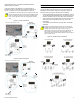
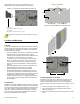
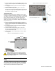
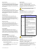
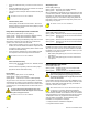
Table Of Contents
- Introduction
- About Magellan and this Manual
- Conventions
- Specifications
- Quick Setup
- Installation
- AC Power
- DC Power
- Backup Battery Pack
- Auxiliary Output
- Telephone Line Connections
- Programmable Outputs (PGMs)
- Hardwire Zone Connections
- WinLoad Connection
- UIP-256 Universal In-Field Programmer Connection
- X10 Transmitter Connection (MG-6160 only)
- Connecting a Paradox Memory Key (PMC-3)
- Location and Mounting
- Connecting the Radio Antenna (MG-6160 only)
- Programming Methods
- WinLoad Installer Upload/Download Software
- Programming Using the Built-in Keypad
- Programming Using a Paradox Memory Key
- User Codes
- User Code Length
- Installer Code
- Maintenance Code
- System Master Code
- Duress Code
- Zone Programming
- Zone Programming Overview
- Zone Definitions
- Zone Options
- Zones 31 and 32 Become Hardwire Zones
- EOL (End-Of-Line) Zones
- Assigning Wireless Zone Transmitters
- Assigning Wireless Doorbells to the Console
- Deleting Assigned Wireless Transmitters
- Viewing Wireless Transmitter Signal Strength
- Assigning Remote Controls
- Programming the Remote Control’s Buttons
- Assigning Wireless Keypads
- Assigning Wireless Repeaters
- Wireless Repeater Options
- Arming and Disarming
- Regular Arming Switches to Stay Arming
- Regular Arming Switches to Force Arming
- Stay Arming Switches to Force Arming
- Timed Auto-Arming
- No Movement Auto-Arming
- Auto-Arming Options
- One-Touch Arming
- Exit Delay
- Bell Squawk on Arm/Disarm with Remote Control
- No Exit Delay when Arming with Remote Control
- Exit Delay Termination
- Follow Zone Switches to Entry Delay 2
- Closing Delinquency Timer
- Stay Arm Siren Delay
- Alarm Options
- Bell Cut-off Timer
- Wireless Transmitter Supervision Options
- Check-in Supervision Options
- Tamper Recognition Options
- Wireless PGM Supervision Options
- Wireless Keypad Supervision Options
- Wireless Repeater Supervision Options
- Wireless PGM Console Supervision Options (Follow Alarm/Follow Bell)
- Backup Alarm Reporting Option
- Panic Alarms
- Reporting and Dialer Settings
- Report Codes
- Console Telephone Numbers
- Console Account Number
- Reporting Formats
- Event Call Direction
- Delay Between Dialing Attempts
- Alternate Dial Option
- Force Dial Option
- Dialing Method
- Pulse Ratio
- Switch to Pulse Dialing on 5th Attempt
- Telephone Line Monitoring (TLM)
- Recent Close Delay
- Auto-Test Report
- Power Failure Report Delay
- Disarm Reporting Options
- Zone Restore Report Options
- RF Jamming Supervision
- Programmable Outputs
- Assigning PGMs
- Setting PGM Function
- Onboard PGM Activation Event
- Onboard PGM Deactivation Event
- Onboard PGM Delay
- PGM Normal State (Onboard Only)
- PGM X10 Option (MG-6160 Only / Onboard Only)
- Wireless PGM Activation Event
- Wireless PGM Deactivation Event
- Wireless PGM Delay
- System Settings
- Software Reset
- Installer Lock
- Console Tamper Supervision
- Console Audible Trouble Warning
- FM Tuner Option (MG-6160 only)
- Daylight Savings Time
- AC Power Failure Warning
- The Trouble Display
- WinLoad Software Settings
- Panel Answer Options
- Panel Identifier
- PC Password
- PC Telephone Number
- Call Back Feature
- Appendix 1: Automatic Report Code List
- Appendix 2: Ademco Contact ID Report Code List
- Index

12 Reference & Installation Manual
4. Slide the Magellan’s open slots labeled D (see Figure 16 on
page 11) onto the wall plate’s tabs labeled B (see Figure 15
on page 11).
5. Gently apply downward pressure to insert the wall plate’s
tabs into Magellan’s open slots.
6. Insert two screws through the wall plate’s screw holes
labeled C and into holes labeled E (see Figure 15 on page 11
and Figure 16 on page 11) in the Magellan back plate. This
will secure the console to the wall.
Tabletop Mounting
Magellan can also be mounted on a tabletop. This is a useful
convenience that allows Magellan to be situated on a nightstand,
desk, kitchen counter, etc. Included with Magellan are two plastic
feet as well as two rubber stops. The plastic feet raise the
Magellan console to a slight angle for easy viewing while the
rubber stops prevent the console from sliding when Magellan is
being used. To do so:
1. Place the console back plate flush against the wall plate.
2. Slide the Magellan’s open slots labeled D (see Figure 16 on
page 11) onto the wall plate’s tabs labeled B (see Figure 15
on page 11).
3. Gently apply downward pressure to insert the wall plate’s
tabs into Magellan’s open slots.
4. Insert two screws through the wall plate’s screw holes
labeled C and into holes labeled E (see Figure 16 on page
11) in the Magellan back plate.
5. Attach the plastic feet and rubber stops as shown in Figure
17 on page 12.
Figure 17: Mounting Magellan on a Tabletop
Tabletop mounting may not be an approved installation
method by local regulations. It is recommended that the
local regulations be verified prior to installing the Magellan
console using this method.
Connecting the Radio Antenna (MG-6160
only)
If the radio’s reception is not very good, connect the supplied
radio antenna to the
ANT terminal on the back of the Magellan
console as shown in Figure 18 on page 12. Move the antenna
around until the spot with the best reception is found.
Figure 18: Connecting the Radio Antenna
Tabletop
Plastic feet
(x2)
Rubber stops
(x2)
Wall
plate
Radio
Antenna
Back view of the Magellan console.