
User's Manual

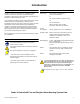
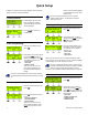
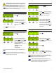
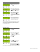
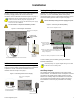
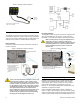
Table Of Contents
- Introduction
- About Magellan and this Manual
- Conventions
- Specifications
- Quick Setup
- Installation
- AC Power
- DC Power
- Backup Battery Pack
- Auxiliary Output
- Telephone Line Connections
- Programmable Outputs (PGMs)
- Hardwire Zone Connections
- WinLoad Connection
- UIP-256 Universal In-Field Programmer Connection
- X10 Transmitter Connection (MG-6160 only)
- Connecting a Paradox Memory Key (PMC-3)
- Location and Mounting
- Connecting the Radio Antenna (MG-6160 only)
- Programming Methods
- WinLoad Installer Upload/Download Software
- Programming Using the Built-in Keypad
- Programming Using a Paradox Memory Key
- User Codes
- User Code Length
- Installer Code
- Maintenance Code
- System Master Code
- Duress Code
- Zone Programming
- Zone Programming Overview
- Zone Definitions
- Zone Options
- Zones 31 and 32 Become Hardwire Zones
- EOL (End-Of-Line) Zones
- Assigning Wireless Zone Transmitters
- Assigning Wireless Doorbells to the Console
- Deleting Assigned Wireless Transmitters
- Viewing Wireless Transmitter Signal Strength
- Assigning Remote Controls
- Programming the Remote Control’s Buttons
- Assigning Wireless Keypads
- Assigning Wireless Repeaters
- Wireless Repeater Options
- Arming and Disarming
- Regular Arming Switches to Stay Arming
- Regular Arming Switches to Force Arming
- Stay Arming Switches to Force Arming
- Timed Auto-Arming
- No Movement Auto-Arming
- Auto-Arming Options
- One-Touch Arming
- Exit Delay
- Bell Squawk on Arm/Disarm with Remote Control
- No Exit Delay when Arming with Remote Control
- Exit Delay Termination
- Follow Zone Switches to Entry Delay 2
- Closing Delinquency Timer
- Stay Arm Siren Delay
- Alarm Options
- Bell Cut-off Timer
- Wireless Transmitter Supervision Options
- Check-in Supervision Options
- Tamper Recognition Options
- Wireless PGM Supervision Options
- Wireless Keypad Supervision Options
- Wireless Repeater Supervision Options
- Wireless PGM Console Supervision Options (Follow Alarm/Follow Bell)
- Backup Alarm Reporting Option
- Panic Alarms
- Reporting and Dialer Settings
- Report Codes
- Console Telephone Numbers
- Console Account Number
- Reporting Formats
- Event Call Direction
- Delay Between Dialing Attempts
- Alternate Dial Option
- Force Dial Option
- Dialing Method
- Pulse Ratio
- Switch to Pulse Dialing on 5th Attempt
- Telephone Line Monitoring (TLM)
- Recent Close Delay
- Auto-Test Report
- Power Failure Report Delay
- Disarm Reporting Options
- Zone Restore Report Options
- RF Jamming Supervision
- Programmable Outputs
- Assigning PGMs
- Setting PGM Function
- Onboard PGM Activation Event
- Onboard PGM Deactivation Event
- Onboard PGM Delay
- PGM Normal State (Onboard Only)
- PGM X10 Option (MG-6160 Only / Onboard Only)
- Wireless PGM Activation Event
- Wireless PGM Deactivation Event
- Wireless PGM Delay
- System Settings
- Software Reset
- Installer Lock
- Console Tamper Supervision
- Console Audible Trouble Warning
- FM Tuner Option (MG-6160 only)
- Daylight Savings Time
- AC Power Failure Warning
- The Trouble Display
- WinLoad Software Settings
- Panel Answer Options
- Panel Identifier
- PC Password
- PC Telephone Number
- Call Back Feature
- Appendix 1: Automatic Report Code List
- Appendix 2: Ademco Contact ID Report Code List
- Index

Paradox Magellan Systems 7
Installation
AC Power
Magellan requires a 12Vac (1A) or 16.5Vac (1A) transformer (not
included) to supply power to the console. Connect the
transformer to the
AC terminals as shown in Figure 1 on page 7.
Magellan can also be powered through a DC power supply.
Connect a 12Vdc to 18Vdc (1A) power supply to the
AC
terminals to power the console. The alternate DC power supply
is not for use in UL installations.
Do not connect to a receptacle controlled by a switch.
Figure 1: Connecting the Transformer
DC Power
Magellan can also be powered through a DC power supply.
Connect a 12Vdc to 18Vdc (1A) power supply to the
AC terminals
to power the console. Connect the transformer to the AC
terminals as shown in Figure 2 on page 7.
Figure 2: Connecting the DC Power Supply
Backup Battery Pack
Magellan uses a backup battery pack to provide power during a
power loss. A 7.2Vdc 1.8Ah NiMH (Nickel Metal Hydride)
rechargeable battery pack is included with the Magellan console.
Connect the battery pack as shown in Figure 3 on page 7.
Connect the backup battery pack after applying AC power.
Figure 3: Connecting the Backup Battery
To order a battery pack, the battery pack’s part number is:
Paradox# 0780100178.
The backup battery can support Magellan during an AC failure
for 24 hours when in standby mode.
Auxiliary Output
The auxiliary power supply terminals can be used to power
motion detectors. The combined current consumption of devices
connected to the auxiliary power supply should not exceed
200mA. If the auxiliary output is overloaded and is shut down,
you must disconnect all loads from the output for at least 10
seconds before reconnecting any load back to the auxiliary
output.
12Vac (1A) to
16Vac (1A)
transformer
Do not use any
switch-controlled
outlets.
Back view of the Magellan
console.
Insert the transformer’s wires into the
AC terminals.
12Vdc to 18Vdc 1A
DC Power Supply
Insert the transformer’s wires
into the
AC terminals.
Back view of the Magellan
console.
Slide in the battery pack horizontally, tilt the battery
pack downward and then tuck it in Magellan’s
battery compartment.
2.
3.
Snap in the battery compartment cover when finished.
Back view of the Magellan console
Insert the backup
battery’s plug into the
connector labeled
BATT.
1.