
Installation Manual

PARADOX.COM
PMD75N
Installation Manual V1.0 DRAFT
Digital Wireless Motion Detector
with Pet Immunity
Introduction
The PMD75N is a wireless, digital, dual-optic passive infrared (PIR) motion
detector designed for compatibility with Paradox alarm systems. It is
immune to pets weighing up to 40 kg (90 lbs). The PMD75N is battery-
powered and offers precision protection and high performance in
maximum security applications.
Overview
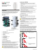
Figure 1 – PMD75N PCB Overview
1. Battery compartment
2. Learn switch
3. Single or Dual Edge Processing Jumper (JP3)
4. Digital Shield Jumper (JP4)
5. Sensors
6. Antenna
7. Alarm LED
8. LED Jumper (JP5)
9. Firmware upgrade connector
10. PCB height tab
11. Height markings
12. Height adjustment screw
13. Anti-tamper switch
14. Battery connector
Location and Mounting
At the recommended height of 2.1m (7 ft) ±10%, the PMD75N provides full
coverage from 1.5m to 11m (5 ft to 35 ft). The installation height is
measured from the center of the detector, refer to Figure 2.
Avoid placing the detector within proximity of the following sources of
interference: reflective surfaces, direct airflow from vents, fans, windows,
sources of steam/oil vapor, infrared light sources, and objects causing
temperature changes such as heaters, refrigerators, and ovens.
Avoid bending, cutting, or altering the antenna or mounting the detector near
or on metal as this may affect signal transmission.
Do not touch the sensor surface as this could result in a detector malfunction.
If necessary, clean the sensor surface using a soft cloth with pure alcohol.
Installing the PMD75N
1. Write down the serial number and the location of the PMD75N for
future reference. This will be needed to enter into the Paradox
BabyWare software.
2. Using a screwdriver, pry the cover apart from the backplate, starting at
the bottom.
3. Using a Phillips screwdriver, loosen the height adjustment screw. Slide
the PCB board up and gently lift the PCB out of its casing.
4. Remove the battery compartment from the backplate.
5. Screw the PMD75N onto the wall through the provided holes.
Note: Ensure that the tamper screw is secured through the respective
tamper hole, refer to D in Figure 1.
6. Reinstall the battery compartment, refer to Powering the Detector
before completing the following steps.
7. Reinstall the PCB and connect the battery connector.
8. Adjust the PCB height, refer to the PCB Height Adjustment section.
Once adjusted, secure the height adjustment screw.
9. Reinstall the top cover.
Powering the Detector
1. Insert three “AAA” batteries into the battery holder while verifying
polarity.
2. Insert the battery holder into the back cover and affix the battery
connector to the PCB.
After connecting the battery connector, a power-up sequence will
begin (lasting 60 seconds). During this time, the red LED will flash
and the detector will not detect an open zone or tamper.
Replacing Batteries
1. Disconnect the battery connector from the PCB. Remove the battery
holder and remove the old batteries.
2. Press and release the anti-tamper switch to ensure that the unit has
powered down.
3. Follow the steps outlined in “Powering the Detector”.
PCB Height Adjustment
The PMD75N is designed for optimal performance at a height of 2.1m (7 ft)
but can be installed at a lower or higher height. After you have installed the
detector, ensure that the adjustable height markings on the right side of the
PCB match the tab inside the back cover. For example, if the detector is
installed at a height of 2.1m (7 ft), the PCB should then be adjusted to
2.1m (7 ft). Ensure to align the desired markings (height) with the back
cover’s plastic tab. If another installation height is called for, readjust the
PCB accordingly. Any PCB adjustments should be followed by a walk-test
of the protected area, refer to Testing the PMD75N.
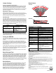
Figure 2 – Beam Dispersion
1
2
3
4
5
6
7
8
10
12
13
14
A
C
B
A
D
A
B
A
B
A - Corner mount
B - Flat surface mount
C - PCB height tab
D - Tamper hole/Corner mount
11
9
2.1m
(7 ft)
2.1m
(7 ft)
3.1m
(10 ft)
2.1m
(7 ft)
1.1m
(4 ft)
2.1m
(7 ft)
B
Unit aims closer, the gap between
beams is smaller. Pet immunity is
compromised.
A
Optimum beam dispersion
A
C
Unit aims further, the gap between
beams is wider. Pet immunity is
compromised.
B
C