SMD2000-24T 24-Port SHDSL Mini DSLAM Installation Instructions Document Number SMD2-A2-GN11-00 July 2005 Contents Software and Firmware License Agreement ................................................. 2 Product Documentation Online ..................................................................... 3 Unpacking and Inspecting the Equipment .................................................... 4 Site Selection Criteria ................................................................................
Software and Firmware License Agreement ONCE YOU HAVE READ THIS LICENSE AGREEMENT AND AGREE TO ITS TERMS, YOU MAY USE THE SOFTWARE AND/OR FIRMWARE INCORPORATED INTO THE PARADYNE PRODUCT. BY USING THE PARADYNE PRODUCT YOU SHOW YOUR ACCEPTANCE OF THE TERMS OF THIS LICENSE AGREEMENT.
b. ANY AND ALL IMPLIED WARRANTIES, INCLUDING WITHOUT LIMITATION IMPLIED WARRANTIES OF MERCHANTABILITY, FITNESS FOR A PARTICULAR PURPOSE AND NON-INFRINGEMENT. Some states or other jurisdictions do not allow the exclusion of implied warranties on limitations on how long an implied warranty lasts, so the above limitations may not apply to you. This warranty gives you specific legal rights, and you may also have other rights which vary from one state or jurisdiction to another. 6.
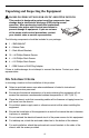
Unpacking and Inspecting the Equipment ! HANDLING PRECAUTIONS FOR STATIC-SENSITIVE DEVICES This product is designed to protect sensitive components from damage due to electrostatic discharge (ESD) during normal operation. When performing installation procedures, however, take proper static control precautions to prevent damage to equipment. If you are not sure of the proper static control precautions, contact your nearest sales or service representative.
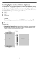
Installing Uplink Interface Modules (Optional) An SMD2000-24T does not require installation of an Uplink Interface Module (UIM) for operational purposes. A UIM offers additional upstream network ports to supplement the two T1 uplink ports already provided. You may wish to install a UIM if your network requires an Ethernet uplink connection or if you require an additional E1 or T1 backhaul.
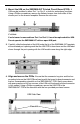
2. Mount the UIM on the SMD2000-24T Printed Circuit Board (PCB). A UIM may be installed in either Port 1 or Port 2, or both for redundancy purposes. Using a Phillips screwdriver, remove the flathead screws from both sides of the chosen port on the chassis faceplate. Remove the slot cover. CAUTION: If a slot cover is removed from Port 1 or Port 2, it must be replaced with a UIM. Do not operate the SMD2000-24T with an open UIM port. 3.
5. Secure the faceplate. Using a Phillips screwdriver, secure the UIM faceplate to the SMD2000-24T faceplate with the two flathead screws included in your UIM packaging. 6. Replace the chassis cover. Replace the chassis cover and secure with the original eight flathead screws as depicted in Step 1 on page 5. Tabletop Installation Procedure To install the SMD2000-24T on a table, desk, shelf, or remote cabinet: 1. Affix the four provided rubber pads to the bottom of the chassis for surface grip.
Rack Installation Procedure To install the SMD2000-24T in a rack: 1. Using a Phillips screwdriver, attach the two provided rack mount brackets to the sides of the SMD2000-24T with the ten provided bracket screws. 2. Mount the chassis onto the rack and secure the rack mount brackets to the sides of the rack using one of the two provided sets of four rack mount screws (whichever size fits the rack being used). 3.
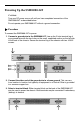
Powering Up the SMD2000-24T CAUTION: Turn your DC power source off until you have completed connection of the SMD2000-24T as described below. Do not operate your SMD2000-24T without a ground connection. Procedure To connect the SMD2000-24T to power: 1. Connect a ground wire to the SMD2000-24T. Line up the 2-hole terminal lug of your ground wire with the two holes on the small, unpainted section on the left side of the back of the chassis. Secure the terminal lug to the chassis with two #10-32 screws. 2.
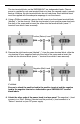
The two terminal blocks on the SMD2000-24T are independent feeds. Chassis power is supplied by only one terminal block at a time; the second supply is merely backup. Likewise, the two terminal blocks do not load-share. Each terminal block must be supplied with the adequate amperage to run the chassis. 4. Using a Phillips screwdriver, remove the left screw from the chosen terminal block (labeled "+" on the chassis).
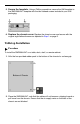
7. Verify the connection. Turn your power source ON. The PWR (power) LED on your SMD2000-24T faceplate will illuminate solid green to indicate that the chassis is receiving power. Connecting the SHDSL RJ21 Cable Procedure To connect the SHDSL cable to the SMD2000-24T RJ21 connector: 1. Configure the SHDSL lines. No configuration is necessary for the SMD2000-24T to operate at default settings.
3. Slide the RJ21 plug connector of your SHDSL cable underneath the hook-and-loop fastener from the right and press it firmly into the RJ21 socket on the chassis. 4. Pull the hook-and-loop fastener strap upward, making sure that it is snug against the RJ21 connector, and then pull the strap back down over itself such that the hook-and-loop fastener layers stick to one another. 5. Screw the left side of the RJ21 plug connector into the jack screw on the left side of the RJ21 socket on the chassis.
The speed and data passing capability of multiple SHDSL lines, as used for one network connection, is cumulative. For example, loop bonding three SHDSL lines for one network connection nets three times the speed and data passing capability of a single-line SHDSL connection. Additionally, use of multiple SHDSL lines for one connection provides automatic backup should one or more lines in the bonded group experience problems or become disabled.
Connecting the Uplink Lines To connect the SMD2000-24T to T1 service: 1. Configure the T1 uplinks. No configuration is necessary for the SMD2000-24T to operate at default settings. However, if you wish to run uplinks at settings other than the SMD2000-24T defaults, configure the uplinks prior to connection. Parameter settings may be changed using the Command Line Interface (CLI), Simple Network Management Protocol (SNMP), or the web-based management system.
Default Settings SHDSL Parameter Defaults Table 1. SHDSL Defaults Parameter Default Backbone-VLAN 0 (off) Circuit Identification n/a (no default) Flood Uplink IP Range 1 0.0.0.0 – 255.255.255.255 IP Range 2 0.0.0.0 – 0.0.0.0 Protocol All Speed 272 kbps VLAN Priority 0 (none) VLAN Range 0 - 0 (off) T1 Uplink Parameter Defaults Table 2.
System and Management Defaults No configuration is necessary for an SMD2000-24T to operate at default settings. Table 3. System and Management Defaults Parameter Default IP Address 192.168.254.252 Subnet Mask 255.255.255.0 Gateway 0.0.0.0 Inband Management disabled Inband Management VLAN ID 0 (off) TFTP (Trivial File Transfer Protocol) on Management IP Address Filter Range 0.0.0.0 – 255.255.255.255 (all) Uplink DSLAM Interconnection 1 (neither/off) User Access Defaults Table 4.
Data Storage Configuration backup is inherent in the SMD2000-24T. Default parameters remain in place unless changed using the CLI, web management system, or SNMP. Memory Parameter configurations are automatically recorded in both Random Access Memory (RAM) and Non-Volatile Random Access Memory (NVRAM). Data stored only in RAM, such as traffic statistics and link up/down time, will be erased if the SMD2000-24T loses power.
SMD2000-24T Template An SMD2000-24T template file records all management and port configurations except IP Address. Table 7. Template Criteria Item Data Needed for Backup Example Host Name DSLAM_IP Address (xxx.xxx.xxx.xxx) 193.166.254.98 Remote Filename NVR_CFG.BIN.[superuser password] nvr_cfg.bin.Password Local Filename user preference smd2000_template.bin SHDSL Port Template A SHDSL port configuration file records all of one port's configurations except Circuit ID. Table 8.
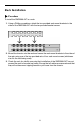
Reset Button The reset button is a small, unmarked button just to the right of the T1 uplink LEDs on the chassis faceplate. The button is recessed and you need a paper clip, mechanical pencil, or similar tool to press it. Reset Button System Reset A system reset will clear all statistical data (stored in RAM) and restart the SMD2000-24T. It will not clear NVRAM; management settings and port configurations will remain unchanged. To perform a system reset, press the Reset Button for one second.
Command Line Interface for 4000E and 12000E BACs, Micro DSLAMs, and Network Extenders User's Guide (Document Number CLI-A2-GB20) or the Network Management System User's Guide (Document Number NMS-A2-GB20) for further information. LED Indicators For purposes of the following descriptions, a pulsing LED blinks steadily at a rate of once per second. A flashing LED blinks at a more rapid, less constant rate. Table 9.
Table 9. LEDs (2 of 3) LNK (10/100 Ethernet Management Link) LK: T1 Uplink Port 1 and 2 State Indication Additional Information Flashing green 100 Mbps management connection is established and active Traffic is flowing at 100 Mbps. Solid green 100 Mbps management connection is established No current traffic flow. Flashing amber 10 Mbps management connection is established and active Traffic is flowing at 10 Mbps.
Table 9. LEDs (3 of 3) AL: T1 Alarm Port 1 and 2 SHDSL LK: Ports 1-24 SHDSL ACT: Ports 1-24 State Indication Additional Information No illumination T1 uplink connection is operational An established T1 uplink connection has no alarm indications and is operational UNLESS the T1 LK LED remains unlit as well, in which case the T1 uplink connection is in Red Alarm. Solid amber Yellow Alarm: The T1 uplink's outgoing connection has been lost; no data is being transmitted.
Pin Assignments SHDSL RJ21 Pinouts Table 10.
10/100BaseT RJ45 Pinouts Table 11. Ethernet RJ45 Connection Pin Connection 1 Rx+ 2 Rx– 3 Tx+ 4 not used 5 not used 6 Tx– 7 not used 8 not used T1 RJ48C Pin Assignments Table 12.
DB9 to 8-Pin Modular Adapter Pinouts To connect the COM port to the DB9 serial port of a PC, use an adapter wired as shown: Table 13. DB9 to 8-Pin Modular Adapter Pinouts Pin 8-Pin Modular Port Direction PC RS232 Serial Port 1 Transmit Data TxD → RxD Receive Data 2 2 Data Set Ready DSR ← RTS Request to Send 7 4 Receive Data RxD ← TxD Transmit Data 3 5 Ground GND ↔ GND Ground 5 6 Data Terminal Ready DTR → CTS Clear to Send 8 Pins not shown are unused.
Technical Specifications Table 14.
EMI Notices United States – EMI Notice This equipment has been tested and found to comply with the limits for a Class A digital device, pursuant to Part 15 of the FCC rules. These limits are designed to provide reasonable protection against harmful interference when the equipment is operated in a commercial environment.
A plug and jack used to connect this equipment to the premises wiring and telephone network must comply with the applicable FCC Part 68 rules and requirements adopted by the ACTA. See installation instructions for details. If the network extender causes harm to the telephone network, the telephone company will notify you in advance that temporary discontinuance of service may be required. But if advance notice isn't practical, the telephone company will notify the customer as soon as possible.
Japan Notice Class A ITE This is a Class A product based on the standard of the Voluntary Control Council for interference by Information Technology Equipment (VCCI). If this equipment is used in a domestic environment, radio disturbance may arise. When such trouble occurs, the user may be required to take corrective actions.
! Important Safety Instructions 1. Read and follow all warning notices and instructions marked on the product or included in the manual. 2. Slots and openings in the cabinet are provided for ventilation. To ensure reliable operation of the product and to protect it from overheating, these slots and openings must not be blocked or covered. 3. Do not allow anything to rest on the power cord and do not locate the product where persons will walk on the power cord. 4.
Warranty, Sales, Service, and Training Information Contact your local sales representative, service representative, or distributor directly for any help needed. For additional information concerning warranty, sales, service, repair, installation, documentation, training, distributor locations, or Paradyne worldwide office locations, use one of the following methods: Internet: Visit the Paradyne World Wide Web site at www.paradyne.com. (Be sure to register your warranty at www.paradyne.com/warranty.
*SMD2-A2-GN11-00* *SMD2-A2-GN11-00* 32