COMSPHERE 392xPLUS MODEMS MODELS 3920PLUS AND 3921PLUS INSTALLATION AND OPERATION MANUAL Document No.
COMSPHERE 392xPlus Modems COMSPHERE 392xPlus Modems Models 3920Plus and 3921Plus Installation and Operation Manual 3920-A2-GN31-30 4th Edition (November 1996) Changes and enhancements to the product and to the information herein will be documented and issued as a new release or a Firmware Update Description document to this manual. For the Model 3920Plus standalone modems, the Universal Service Order Code (USOC) for Permissive mode is RJ11C. The Canadian equivalent to RJ11C is CA11A.
Safety Instructions Important Safety Instructions 1. Read and follow all warning notices and instructions marked on the product or included in the manual. 2. This product is intended to be used with a three-wire grounding type plug – a plug which has a grounding pin. This is a safety feature. Equipment grounding is vital to ensure safe operation. Do not defeat the purpose of the grounding type plug by modifying the plug or using an adapter.
COMSPHERE 392xPlus Modems Notices
Table of Contents Preface Objectives and Reader Assumptions . . . . . . . . . . . . . . . . . . . . . . . . . vii How to Use This Manual . . . . . . . . . . . . . . . . . . . . . . . . . . . . . . . . . . vii Related Documents . . . . . . . . . . . . . . . . . . . . . . . . . . . . . . . . . . . . . . viii 1. Introduction Overview . . . . . . . . . . . . . . . . . . . . . . . . . . . . . . . . . . . . . . . . . . . . . . COMSPHERE 392xPlus Models . . . . . . . . . . . . . . . . . . . . . . . . . . .
COMSPHERE 392xPlus Modems Poll List Branch . . . . . . . . . . . . . . . . . . . . . . . . . . . . . . . . . . . . . . . . . Control Branch . . . . . . . . . . . . . . . . . . . . . . . . . . . . . . . . . . . . . . . . . . Test Branch . . . . . . . . . . . . . . . . . . . . . . . . . . . . . . . . . . . . . . . . . . . . Sub-Network Health and Status Branch . . . . . . . . . . . . . . . . . . . . . . Call Setup Branch . . . . . . . . . . . . . . . . . . . . . . . . . . . . . . . . . . . . . . .
Table of Contents List of Figures Figure 1-1 1-2 1-3 2-1 2-2 2-3 2-4 3-1 3-2 3-3 3-4 3-5 3-6 3-7 3-8 3-9 3-10 4-1 C-1 C-2 C-3 C-4 G-1 G-2 G-3 G-4 G-5 G-6 G-7 G-8 G-9 G-10 3920-A2-GN31-30 Page Model 3920Plus Standalone Singleport and Multiport Modems . . . . . . . . . . . . . . . 1-3 Model 3921Plus Singleport Modem . . . . . . . . . . . . . . . . . . . . . . . . . . . . . . . . . . . . . 1-5 Model 3921Plus Multiport Modem . . . . . . . . . . . . . . . . . . . . . . . . . . . . . . . . . . . . . .
COMSPHERE 392xPlus Modems List of Tables Table 1-1 1-2 3-1 3-2 3-3 3-4 3-5 3-6 3-7 3-8 3-9 4-1 4-2 4-3 4-4 4-5 4-6 4-7 4-8 4-9 4-10 4-11 4-12 4-13 4-14 5-1 5-2 5-3 6-1 6-2 6-3 6-4 6-5 6-6 6-7 B-1 B-2 B-3 B-4 B-5 iv Page 392xPlus Operational Modes . . . . . . . . . . . . . . . . . . . . . . . . . . . . . . . . . . . . . . . . . . . 1-7 Technical Specifications for 392xPlus Modems . . . . . . . . . . . . . . . . . . . . . . . . . . . . 1-13 392xPlus DCP LEDs . . . . . . . . . . . . . . . . . . . . . . . .
Table of Contents Table B-6 B-7 C-1 C-2 D-1 D-2 E-1 F-1 3920-A2-GN31-30 Page Online Operation . . . . . . . . . . . . . . . . . . . . . . . . . . . . . . . . . . . . . . . . . . . . . . . . . . . . B-5 Mux Operation . . . . . . . . . . . . . . . . . . . . . . . . . . . . . . . . . . . . . . . . . . . . . . . . . . . . . . B-5 EIA-232-D Pin Assignments . . . . . . . . . . . . . . . . . . . . . . . . . . . . . . . . . . . . . . . . . . . C-2 VF Connector Pin Assignments . . . . . . . . . . . . . . . . . .
Preface Objectives and Reader Assumptions This manual describes how to install and operate the COMSPHEREr Model 3920Plus standalone and Model 3921Plus carrier-mounted modems. Users of this manual must have a basic understanding of modems and their operation. How to Use This Manual Chapter 1 provides technical specifications, information about the four 392xPlus models, the modem features, and the government requirements for using these modems.
COMSPHERE 392xPlus Modems Related Documents 3000-A2-GA31 COMSPHERE 3000 Series Carrier, Installation Manual 3610-A2-GZ45 3600 Hubbing Device, Feature Number 3600-F3-300, Installation Instructions 3920-A2-GK41 COMSPHERE 392xPlus Modems, Models 3920Plus and 3921Plus, Installation Instructions 3920-A2-GK40 COMSPHERE 3900 Series Modems, Model 3921Plus, Ferrite Choke Installation Instructions Call your sales representative to order additional product documentation.
Introduction Overview . . . . . . . . . . . . . . . . . . . . . . . . . . . . . . . . . . . . . . . . . . . . . . . . . . . . COMSPHERE 392xPlus Models . . . . . . . . . . . . . . . . . . . . . . . . . . . . . . . . . . Model 3920Plus Standalone Singleport Modem . . . . . . . . . . . . . . . . . . . Model 3920Plus Standalone Multiport Modem . . . . . . . . . . . . . . . . . . . . Model 3921Plus Carrier-Mounted Singleport Modem . . . . . . . . . . . . . . Model 3921Plus Carrier-Mounted Multiport Modem . . .
COMSPHERE 392xPlus Modems COMSPHERE 392xPlus Models The COMSPHERE 392xPlus modem is available in the following four models: • Model 3920Plus standalone singleport modem (model no. 3920-A1-41x). • Model 3920Plus standalone multiport modem (model no. 3920-A1-40x). • Model 3921Plus carrier-mounted singleport modem (model no. 3921-B1-01x). • Model 3921Plus carrier-mounted multiport modem (model no. 3921-B1-00x).
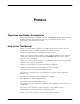
Introduction Model 3920Plus Singleport and Multiport Housing DIAGNOSTIC CONTROL PANEL LCD AND KEYPAD SPEAKER POWER SUPPLY STATUS INDICATORS POWER CORD Singleport Modem Back Panel Multiport Modem Back Panel POWER ON/OFF DTE 4 POWER ON/OFF DTE 3 POWER IN DTE 2 NMS DTE 1 DIAL LEASED POWER IN NMS DTE 1 DIAL LEASED 496-14684-01 Figure 1-1.
COMSPHERE 392xPlus Modems Model 3921Plus Carrier-Mounted Singleport Modem The Model 3921Plus is a carrier-mounted singleport modem (Figure 1-2) capable of either 4-wire/2-wire leased-line or dial operation. The modem installs into a COMSPHERE 3000 Series Carrier, occupying a single slot. The modem’s faceplate has sixteen (16) LED status indicators for displaying modem activity and an audio speaker jack for the carrier’s optional speaker.
Introduction FACEPLATE Status Pwr Alrm 142 Test BACK CONNECTOR PLATE Dial 125 RI Busy Serv EIA232/V.24 CONNECTOR EIA232/V.24 EDGE CARD CONNECTOR RXD 105 RTS 106 CTS 107 DSR 108 DTR 109 LSD GROUNDING TAB FUTURE USE Front Panel Spkr V.35 (3600/3500) TXD 104 RS366A/V.25 (3800) 103 EIA232/V.24 SQ FUTURE USE 3921Plus 496-14178a-04 Figure 1-2.
COMSPHERE 392xPlus Modems FACEPLATE Status Pwr EDGE CARD CONNECTORS Alrm 142 Test Dial 125 RI Busy Serv BACK CONNECTOR PLATES SQ 1 3 Port 4 RXD 105 RTS 106 CTS 107 DSR 108 DTR 109 LSD PORT 1 PORT 3 DTE A 104 DTE B TXD DTE A 103 DTE B 2 Front Panel Spkr PORT 2 PORT 4 3921Plus 49614423a-03 Figure 1-3.
Introduction 392xPlus Operational Modes The 392xPlus operational modes determine how your modem performs in various applications. These operational modes are determined by your modem model and the selected configuration options. There are two operational modes: • Singleport mode. Operates on both the singleport and multiport modems. Singleport mode is the only operational mode for the singleport modem. For the multiport modem, it is in effect when the MUX mode configuration option is set to Disable.
COMSPHERE 392xPlus Modems • Network management system (NMS) support through the COMSPHERE 6800 or 6700 Series NMS using Advanced Diagnostic protocol (ADp). • Automatic and manual backup with standby capabilities for 4-wire/2-wire leased-line applications. (The backup facility may be either a 2-wire dial line or a 2-wire leased line.) 392xPlus Singleport Features Features specific to 392xPlus singleport modems are: • Four-wire/two-wire leased-line modulations. • Dial-line modulations.
Introduction Dual-Leased Backup Dual-Leased Backup is available in all 392xPlus modems. It enables a 2-wire leased line to be used as the backup facility instead of the normal 2-wire dial line. Plug the leased line into the jack labeled DIAL on the back panel of the modem (see Figure 2-1 in Chapter 2), and enable the Dual_Leased_Ln configuration option. (Refer to the Multiport Mode — Leased Line or the Singleport Mode — Leased Line section in Chapter 4 for configuration options.
COMSPHERE 392xPlus Modems The CCITT standard for V.34 modulation includes dial- or leased-line operation. For proper leased-line operation, one modem must be designated as the answer modem while the other modem must be designated as the originate modem. The V.34 standard also includes asymmetric rates, automatic adjustment of the transmit power level, and automatic adjustment of the symbol (baud) rate for optimal data throughput.
Introduction Government Requirements and Equipment Return Certain governments require that instructions pertaining to modem connection to the public switched telephone network be included in the installation and operation manual. Specific instructions are listed in the following sections. United States NOTICE TO USERS OF THE PUBLIC SWITCHED TELEPHONE NETWORK 1. This equipment complies with Part 68 of the FCC rules.
COMSPHERE 392xPlus Modems 9. If you experience trouble with this equipment, please contact your sales or service representative (as appropriate) for repair or warranty information. If the product needs to be returned to the company service center for repair, contact them directly for return instructions using one of the following methods: • Via the Internet: Visit the Paradyne World Wide Web site at http://www.paradyne.
Introduction Technical Specifications Table 1-2 shows the technical specifications for the 392xPlus modems. Table 1-2 (1 of 2) Technical Specifications for 392xPlus Modems Description Specifications APPROVALS Model 3920Plus, 3921Plus, and COMSPHERE 3000 Series Carrier Refer to the product labeling or contact your service representative. COMPATIBILITY Leased-Line Modulations: Paradyne V.34 (33,600, 31,200 bps) CCITT V.
COMSPHERE 392xPlus Modems Table 1-2 (2 of 2) Technical Specifications for 392xPlus Modems Specifications Description POWER CONSUMPTION Model 3920Plus Singleport 6 watts (typical, including power supply, speaker off) Model 3921Plus Singleport 4 watts (typical, each card) (Speaker consumption is approximately 1 watt at high volume.
Modem Installation Overview . . . . . . . . . . . . . . . . . . . . . . . . . . . . . . . . . . . . . . . . . . . . . . . . . . . . 392xPlus Modem Package . . . . . . . . . . . . . . . . . . . . . . . . . . . . . . . . . . . . . . . Customer-Supplied Equipment . . . . . . . . . . . . . . . . . . . . . . . . . . . . . . . . . Model 3920Plus Modem Installation . . . . . . . . . . . . . . . . . . . . . . . . . . . . . . . Connecting Cables to the Model 3920 Modem . . . . . . . . . . . . . . . . . . . . . . .
COMSPHERE 392xPlus Modems For the carrier-mounted models • Installation instructions • Model 3921Plus modem • One (singleport) or two (multiport) connector plates with two DB-25-S edge card connectors on each plate If any hardware components are damaged, notify your service representative. Return equipment using the procedures described in the Government Requirements and Equipment Return section of Chapter 1.
Modem Installation Model 3920Plus Modem Installation Before installing your standalone modem, make sure your installation site is clean and well-ventilated. Allow space around the modem for installing cables and telephone cords, and make sure the modem is located within reach of the ac power outlet. The distance between your modem and DTE should be minimized if DTE data rates exceed 19,200 bps.
COMSPHERE 392xPlus Modems DB-25-S CONNECTORS DTE 2 DTE 3 LEASED DIAL 8-POSITION, 8-CONDUCTOR PLUG FOR LEASED-LINE NETWORK OPERATION 6-POSITION, 4-CONDUCTOR PLUG FOR PERMISSIVE DIAL NETWORK OPERATION DTE 1 DTE 4 NMS PWR ON OFF DB-25-P CONNECTOR FOR DATA TERMINAL EQUIPMENT OPERATION SUB-MINIATURE, 4-POSITION, 4-CONDUCTOR PLUG FOR NETWORK MANAGEMENT SYSTEM OPERATION POWER SUPPLY POWER CORD NOTE: THE DIAL JACK IS ALSO USED FOR 2-WIRE LEASED BACKUP. Figure 2-1.
Modem Installation Power Supply Connection Use the following steps to connect the modem to an ac power outlet: 1. Make sure the modem is powered OFF. 2. Insert the power supply’s 8-pin DIN connector into the modem’s back panel dc power receptacle, labeled PWR (Figure 2-1). 3. Connect the power cord to the power supply. 4. Connect the power cord to a grounded ac power outlet. Leased-Line Connection Use the following steps to connect the leased-line network interface: 1.
COMSPHERE 392xPlus Modems Network Management System Connection Use the following steps to connect the modem to the network management system (NMS) interface: 1. Insert the sub-miniature, 4-conductor modular plug of the 3600 Hubbing Device into the jack labeled NMS (Figure 2-1). Refer to Document Number, 3610-A2-GZ45, 3600 Hubbing Device, Feature Number 3600-F3-300, Installation Instructions, for a description of the 3600 Hubbing Device. Installation for the 3920Plus is the same as for the 3610 DSU. 2.
Modem Installation SDU is required when the modems in the carrier are controlled by an NMS, or when multiple carriers in a cabinet configuration are to be controlled by a single shared diagnostic control panel (SDCP). The SDCP of the COMSPHERE 3000 Series Carrier is the user interface to the Model 3921Plus modem. A single SDCP can control up to eight carriers. The installation of a Model 3921Plus modem varies slightly if an SDCP is installed on the front of the carrier.
COMSPHERE 392xPlus Modems 3000 SERIES CARRIER SDU MODEL 3921Plus SINGLEPORT MODEM LATCH CIRCUIT CARD GUIDES 3000 SERIES CARRIER SDU MODEL 3921Plus MULTIPORT MODEM LATCH CIRCUIT CARD GUIDES 495-14708 Figure 2-3.
Modem Installation If the Model 3921Plus modem is to communicate with an installed SDCP, install the modem as described above and perform the following steps: 1. Press the Select key on the SDCP. The Carr:Slot screen appears with the cursor on the slot selection position (01 on the first LCD line in following screen example). Carr:Slot: ↑ ↓ F1 F2 1:01A 1:01A F3 2. Press the F1 ( " ) or F2 ( # ) key until the slot number you want appears. 3.
COMSPHERE 392xPlus Modems 6. Once you have determined that the modem is installed properly and completed its power-up self-test, rotate the circuit pack lock until it covers the faceplate latch (Figure 2-4) and tighten the retention screw on the circuit pack lock. This prevents the modem from accidently being removed once it is installed in a carrier. 7. Configure the modem as described in the Selecting Factory Configuration Options section earlier in this chapter.
Modem Installation Removing and Replacing the Model 3921Plus Modem CAUTION When removing the Model 3921Plus modem from the carrier, always use a ground strap when handling the modem. Always store the Model 3921Plus modems in an antistatic bag when it is removed from the carrier. It is not necessary to power down the carrier to remove and replace the Model 3921Plus modem. Perform the following steps: 1. Rotate the circuit pack lock until the release tab is exposed (Figure 2-4). 2.
COMSPHERE 392xPlus Modems configuration, then you must change the factory setting using either the modem’s DCP (as described in the following sections) or the AT command set. The purpose of having preset configurations is so that you can have a “head start” in getting your modem operating and reducing the amount of time required to configure your modem. For a better understanding of DCP operation and factory preset configuration options, refer to Chapter 4, DCP Configuration.
DCP Operation Overview . . . . . . . . . . . . . . . . . . . . . . . . . . . . . . . . . . . . . . . . . . . . . . . . . . . . Diagnostic Control Panels . . . . . . . . . . . . . . . . . . . . . . . . . . . . . . . . . . . . . . . Model 3920Plus Diagnostic Control Panel . . . . . . . . . . . . . . . . . . . . . . . . Model 3921Plus Faceplate and Shared Diagnostic Control Panel (SDCP) . . . . . . . . . . . . . . . . . . . . . . . . . . . . . . . . . . . . . . Status Indicators . . . . . . . . . . . . . . . .
COMSPHERE 392xPlus Modems Test Branch . . . . . . . . . . . . . . . . . . . . . . . . . . . . . . . . . . . . . . . . . . . . . . . . . . . Abort . . . . . . . . . . . . . . . . . . . . . . . . . . . . . . . . . . . . . . . . . . . . . . . . . . . . . Self . . . . . . . . . . . . . . . . . . . . . . . . . . . . . . . . . . . . . . . . . . . . . . . . . . . . . . . Loc Analog Loop . . . . . . . . . . . . . . . . . . . . . . . . . . . . . . . . . . . . . . . . . . . . Rem Digital Loop . . . . . . . . . . . .
DCP Operation Model 3920Plus Diagnostic Control Panel The diagnostic control panel (DCP) of the Model 3920Plus modem (Figure 3-1) contains status indicators, pushbutton-type keys, an LCD, and speaker grill. F1 PWR F3 F2 ALRM DIAG DTR RTS CTS TXD LSD RXD 108 105 106 103 109 104 SQ TEST RATE DIAL COMSPHERE 3920Plus 142 496-14412-02 Figure 3-1.
COMSPHERE 392xPlus Modems MULTIPORT SINGLEPORT Status Status Status OK Pwr Alrm Alrm Diag In Diag Out 142 Pwr Alrm 142 Test Dial 125 Test Dial 125 RI RI Busy Busy Serv Serv SQ SQ 1 3 Port 2 4 103 TXD 103 TXD 104 RXD 104 RXD 105 RTS 105 RTS 106 CTS 106 CTS 107 DSR 107 DSR 108 DTR 108 DTR 109 LSD 109 LSD Front Panel Front Panel Spkr Spkr 3921Plus 3921Plus SDU CARRIER SLOTS 1–16 SDU 1 2 3 4 5 6 7 8 9 10 11 12 13 14 15 16 Select
DCP Operation Table 3-1 (1 of 2) 392xPlus DCP LEDs Label Color Pwr green Alrm red Indicates Power has been applied to the modem. Flashing – A major alarm has been detected in a remote 392xPlus modem. ON – A major alarm has been detected in the local modem. (For Health and Status alarm conditions, refer to Table 3-6 in the Device Health and Status section of this chapter.) Diag (3920Plus only) green The modem is receiving diagnostic communications (either a command or a status poll).
COMSPHERE 392xPlus Modems Table 3-1 (2 of 2) 392xPlus DCP LEDs Label Color Indicates ON – The selected port* is one of the mux ports (either 1, 2, 3, or 4). Port* 1,2,3,4 (3921Plus multiport only) green TXD/103* green The modem is receiving data from the selected port* to transmit. (ON equals space.) RXD/104* green Data is being transferred to the selected port*. (ON equals space.) RTS/105* green RTS signal is ON for the selected port*.
DCP Operation Diagnostic Control Panel Operation The 392xPlus modem’s diagnostic control panel (DCP) is the user interface to all functions used to configure and control the modem. In addition to the status LEDs, this interface includes the liquid crystal display (LCD) and keypad (Figure 3-3). LCD TOP LINE MOVES UP ONE LEVEL FROM CURRENT DISPLAY HIDDEN CHOICE INDICATOR Leased:28.
COMSPHERE 392xPlus Modems Other Indicators Other indicators may turn on depending on existing conditions, such as error detection, informational alerts, and warnings. These indicators appear on the top or bottom line of the LCD. Remote Mode Indicator If the local 392xPlus modem establishes a connection with the remote 392xPlus modem via the Remote branch, then appears in the upper right corner of the LCD top line on both modems.
DCP Operation F1 F2 F3 Keys Function keys F1, F2, and F3 select the LCD choice that appears above the function key. Refer to the Summary section in Chapter 4 for the exception. If the displayed LCD choice spans more than one function key, then any of the function keys select that choice. NOTE In the screen examples, the F1 key is highlighted where multiple function keys select the choice.
COMSPHERE 392xPlus Modems The menu tree contains the following branches: Status — Used to monitor the current status of the VF line and DTE interface as well as view the identity of the modem. Configure — Used to change and save the modem’s configuration options. PList — (Poll List) Used to identify downstream modems in order to support multipoint health and status polling and multipoint link download broadcasting. Control — Used to control the modem’s hardware and software functions.
DCP Operation Top-Level Menu Status and Operational Messages Access to all menu tree branches from the DCP begins at the Top-Level menu, the head of the menu hierarchy. The LCD’s top line identifies the modem status, as listed in Table 3-3, while the bottom line displays the main menu tree branches as well as operational and security messages, as listed in Table 3-4 and Table 3-5.
COMSPHERE 392xPlus Modems Table 3-3 (2 of 3) Top-Level Menu Status Status Call Failure Message Indicates Busy Signal The answering modem is busy. Delayed Number { As a result of failed call attempts, this number can not be called at this time. Please try again later. Dial Line in Use The modem is operating on dial networks when another call attempt is issued. Forbidden Number { As a result of failed call attempts, this number can not be called again.
DCP Operation Table 3-3 (3 of 3) Top-Level Menu Status Status Call Disconnect Firmware Download Result AT Command Reset 3920-A2-GN31-30 Message Indicates ATH Disconnect The modem has disconnected due to an ATH command. Bad Lines Disc The modem has disconnected because the lines do not support the modulation and/or data rate selected. No Carrier Disc The modem disconnects due to the loss of carrier signal from the remote modem.
COMSPHERE 392xPlus Modems Messages listed in Table 3-4 are common operational messages that occur during modem operation. These messages normally appear on the second line of the LCD. Table 3-4 Common Operational Messages Common Operational Message Indicates Please Wait... A command to a local device takes more than two seconds to complete. Command Sent... A command is sent to a remote modem. No Rem Response or Remote Modem Fail A remote modem does not respond to a command within 5 seconds.
DCP Operation The Top-Level menu’s main branches appear on the LCD in the order of Status, Configure, Control, Test, Call Setup, Talk/Data, Security, and Remote. These branches are discussed in this chapter except for the Configure branch which is reserved for Chapter 4, DCP Configuration, and the Security branch which is reserved for Chapter 6, Dial Access Security. Quick Configuration Display The Quick Configuration display indicates the basic operational characteristics of the modem. Leased:28.
COMSPHERE 392xPlus Modems The following provides information about the Quick Configuration LCD display. a Displays the network position of the modem. The letter C indicates this is a control modem, and T indicates this is a tributary modem. bbb Displays the network management address of the modem. The valid address field range is from 001 to 256. c Displays the DTE mode.
DCP Operation Status Branch The Status branch of the Top-Level menu allows you to view the current status of the leased-line or dial connection, the identity (for example, serial number and model number) of your equipment, and the DTE interface.
COMSPHERE 392xPlus Modems Device Health and Status (DeviceHS) DeviceHS provides a ‘‘snapshot” of current modem alarms which are active at the time the DeviceHS function is selected. To access DeviceHS from the Status branch, make the following selection: Status: DeviceHS F1 F2 > VF F3 Select DeviceHS. Device HS: Major F1 F2 > Minor F3 If alarms are present, press the appropriate function key to view the messages associated with these alarms (Table 3-6).
DCP Operation Table 3-6 (2 of 3) Health and Status Messages Type Status Dial Thresh* Message Indicates Subtree Truncate Downstream health and status information has been truncated because it overflowed system limits. There is a large amount of health and status information in the subnetwork. Test Mode The modem or an upstream device is running a disruptive test. Disabled The modem’s DTE port has been disabled. On Dial Backup The modem is operating in Dial Backup mode.
COMSPHERE 392xPlus Modems Table 3-6 (3 of 3) Health and Status Messages Type Security Ports 1 Ports 2 Ports 3 Ports 4 Message Indicates Database Reset The security database has been reset (passwords erased). Password Protect Security password protection is enabled. Mode Change There has been a change in security mode. (Refer to Chapter 6, Dial Access Security.) Password Change A security password has been changed. Database Change The security database containing passwords has been changed.
DCP Operation Displaying VF Conditions Status:VF Display F1 F2 Clear F3 To display VF conditions, select Display from the Status:VF screen. Status:VF SigQual=Excelent F1 F2 > F3 If the modem is receiving a signal, the signal quality appears on the LCD’s bottom line. If the modem is not receiving a signal, the message No Signal appears. Press the key to scroll and view the VF conditions. NOTE Not all conditions are available at 4800 bps.
COMSPHERE 392xPlus Modems EchoFreqOff Echo Frequency Offset displays the frequency offset of the far end echo. This parameter appears for V.34, V.32 terbo, V.32bis, and V.32 modulations (in 2-wire only). Phase Hts Phase Hits reports the total hit count of sudden uncontrolled changes in the phase of the receive signal for the past 15 minutes. This parameter appears for V.32 terbo, V.32bis, and V.32 modulations (in 4-wire only).
DCP Operation VF Counter Clear Command Complete F1 F3 F2 The message Command Complete appears on the LCD’s bottom line indicating the VF Counters are cleared. To exit VF and remain in the Status Branch, press the menu, press the key. key. To exit and return to the Top-Level Identity Identity displays the modem’s serial number, model number, firmware revision level, hardware revision number and firmware part number.
COMSPHERE 392xPlus Modems DTE DTE displays the state and/or activity of the following interface leads: LSD, DTR, DSR, TST, TXD, RXD, RTS, and CTS. The interface leads status is updated every 5 seconds. To access DTE from the Status branch, make the following selections: Status: Identity F1 Press the DTE F2 F3 key until DTE appears. Select DTE. Select DTE Port > Port1 Port2 F1 F2 F3 Select the appropriate port by pressing the corresponding function key.
DCP Operation V.34 When running V.34 modulation, this function displays information about the modem’s receiving and transmitting data rate, symbol rate, transmitting level, and asymmetric rate. NOTE The V.34 status display is available only when the modem is configured for V.34 modulation. To access V.34 from the Status branch, make the following selection: Status: DTE F1 V.34 F2 F3 Select V.34. Status: V.
COMSPHERE 392xPlus Modems Backup The Status Backup function displays the configuration of the modem’s current operating line facility and the configuration and condition of the inactive line. NOTE The modem’s rear panel has two line interface jacks: LEASE and DIAL (see Figure 2-1 in Chapter 2). The jack labeled LEASE is the APL primary interface and accepts either 2-wire or 4-wire APL. The jack labeled DIAL is the backup interface and accepts either 2-wire APL (Dual Lease Line) or Dial lines.
DCP Operation Table 3-7 provides information about the Status Backup screens. The first column lists all possible configurations for the modem’s currently active line. The second column lists all possible configurations for the modem’s inactive lines. The third column provides information about the inactive line condition. XXXX represents the condition code of the inactive line.
COMSPHERE 392xPlus Modems Options The Options Status function displays all optional firmware features currently installed in the modem. If no firmware options are installed, None_Installed appears on the LCD. To access Options from the Status branch, make the following sections: Status: DTE F1 Press the Options F3 F2 key until Options appears. Select Options. Options:Status V.29 F1 F2 > V.33 F3 If optional features are installed in the modem, they appear on the LCD’s bottom line.
DCP Operation Record Status Display Clear F1 F2 F3 To display sequence faults, select Display. Record Number 1 Modem O.K. F1 F2 F3 The LCD displays the first sequence fault field. (Sequence fault fields range from 1 to 8 and are key to view the remaining fields. identified by a number in the upper right corner.) Press the The message Modem O.K. appears if no sequence faults have occurred. To remove sequence fault records from both the LCD and nonvolatile memory, select Clear. The message Modem O.K.
COMSPHERE 392xPlus Modems Select Nxt to scroll through the entries in the Service Log. To exit this function and remain in the Status branch, press the Top-Level menu, press the key. key. To exit and return to the Configure Branch The Configure branch of the LCD allows you to change and save the modem’s configuration options. For configuration options and DCP configuration procedures, refer to Chapter 4, DCP Configuration.
DCP Operation Leased:28.8 PList Control F1 Press the F2 F3 key until PList appears. Select PList. Within a network link, a control modem can communicate with a tributary modem by using the tributary modem’s network management address for polling functions. Each TMp tributary modem must have a different network management address. Refer to the Misc section in Chapter 4 for a description of the network management address (NetMngmtAddress) configuration option.
COMSPHERE 392xPlus Modems Select Nxt to scroll through the entries in the Active or Skip poll lists. To exit this function and remain in the PList Display branch, press the to the Top-Level menu, press the key. key. To exit and return Clear The Clear function does not appear in Remote mode. Clear deletes the modem’s poll list. To access Clear from the PList branch, make the following selection: Poll List: Display F1 > Clear F2 F3 Select Clear.
DCP Operation To implement Change, select the appropriate function (Active, Delete, or Skip). (For Skip, you will need to press the key until Skip appears.) Poll List:yyyyyy Ent xxx F1 F2 F3 The function field (yyyyyy) displays the function selected (Active, Delete, or Skip). The address field (xxx) displays the network management address of the modem to be changed. The valid address field range is from 001 to 256.
COMSPHERE 392xPlus Modems The message Command Complete appears on the LCD to indicate that the tributary modem will be added to the control modem’s poll list. To exit this function and remain in the PList branch, press the key. Top-Level menu, press the key. To exit and return to the Acquire The Acquire function does not appear in Remote mode. Acquire allows you to acquire an active poll list consisting of all modems that are one tier downstream.
DCP Operation Poll List:Acquir Num Acquired F1 yyy F3 F2 The number field (yyy) indicates the total number of devices acquired for the poll list. To exit this function and remain in the PList branch, press the key. Top-Level menu, press the key. To exit and return to the Control Branch The Control branch of the Top-Level menu allows you to manage hardware and software functions, such as speaker volume, reset, busy out, and firmware download.
COMSPHERE 392xPlus Modems Speaker Speaker allows you to make temporary adjustments to the modem’s speaker volume. Upon a reset, speaker volume returns to its configured setting. For more information on speaker settings, refer to the Misc section in Chapter 4. To access Speaker from the Control branch, make the following selection: Control: Speaker F1 > Reset F2 F3 Select Speaker. Speaker Control > Off Low Med F1 Press the F2 F3 key and appropriate function keys to choose the desired selection.
DCP Operation Reset Reset causes the modem to stop operation and perform a complete program restart. The modem begins the power-up test sequence that ends with the Top-Level menu displayed on the LCD. Configuration options stored in an Active (Saved) configuration area are copied to the Active (Operating) configuration area. To access Reset from the Control branch, make the following selection: Control: Speaker F1 > Reset F2 F3 Select Reset.
COMSPHERE 392xPlus Modems Data Stream Port1 Disable F1 F3 F2 The port field (for example, Port1) displays the selected port. The available Data Stream action (Disable or Enable) appears on the second line of the LCD beside the port field. If the modem’s data transmitter is enabled, the word Disable appears to indicate that you may disable the data transmitter by selecting this action. To change the modem’s data stream, press the F2 key.
DCP Operation Select DS Port All F1 F2 > F3 To change the data stream on all ports again, press the F1 key. or To exit this function and remain in the Control branch, press the Top-Level menu, press the key. key. To exit and return to the EIA LEDs This function allows the front panel EIA LEDs to display and change the activity of a selected digital interface. Use the EIA LEDs function to change the port that controls the front panel LED.
COMSPHERE 392xPlus Modems Press the F1 key until the appropriate digital interface appears. Select the appropriate interface by pressing the corresponding function key. After selecting the desired interface, the message Command Complete appears on the bottom line of the LCD and the selected interface appears in the xxxxx field. NOTE The Port 1 interface is the only display allowed on the 3921Plus modem in Singleport mode, therefore the entire EIA LEDs branch is masked.
DCP Operation Control: RemoveMakeBusy F1 F2 F3 Press any function key to select RemoveMakeBusy. The message Command Complete appears on the LCD. Service Line/Disconnect Service Line The Service Line/Disconnect Service Line is only available in Models 3921-B1-001 and 3021-B1-011. The Service Line function allows you to switch a specific Model 3921Plus installed in a COMSPHERE 3000 Series Carrier from normal leased or dial operation to service-line operation.
COMSPHERE 392xPlus Modems To disconnect the modem from the service line and resume normal operation, press the key (returning to Control branch). From the Control branch, press the key until DiscServiceLine appears. Control: DiscServiceLine F1 F2 F3 Press F1 (DiscServiceLine). The call and service line disconnect and the message Command Complete appears.
DCP Operation Control: Download_Code F1 F3 F2 Press the key until Download_Code appears. Press any function key to select Download_Code. The DwnLoadSoftware screen appears. DwnLoadSoftware > Clone_Remote F1 F3 F2 Press any function key to select Clone_Remote. The next screen to appear is determined by the modem’s configuration.
COMSPHERE 392xPlus Modems From the Choose DLL Type screen, press the F1 key to select SC_Clone to request the transfer of an exact copy of the tributary modem’s firmware to the VF connected control modem. Proceed to the section titled Implementing a Clone Remote Operation, which follows the descriptions of multipoint cloning operations.
DCP Operation Clone Remote in Multipoint Configurations A Trellis Multipoint (TMp) control modem can be used to download firmware to just one tributary modem (Single) or to all of its tributary modems (Multiple). NOTE A Trellis Multipoint (TMp) tributary modem cannot download firmware to its control modem. To download firmware to a TMp control modem use a point-to-point dial connection, an NMS, or a PC controller.
COMSPHERE 392xPlus Modems Cloning a Single TMp Remote Choose DLL Type > Single Multiple F1 F3 F2 Press the F1 key to select Single Clone Remote. Choose Address: Ent xxx F1 F2 F3 The address field (xxx) displays the network management address of the modem that receives the download. The valid address field range is from 001 to 256. and keys to position the cursor To increment digits within the address field (xxx), use the ( _ ) under the digit to be incremented.
DCP Operation Cloning a Multiple TMp Remote Choose DLL Type > Single Multiple F1 F2 F3 Press the F3 key to select Multiple Clone Remote. After completing this action, proceed to the next section titled Implementing a Clone Remote Operation. Viewing Multiple TMp Clone Results Choose DLL Type > MPtCloneResults F1 F2 F3 From the Choose DLL Type screen, press the key until the MPtCloneResults screen appears to view the results of the last multiple TMp clone operation.
COMSPHERE 392xPlus Modems Implementing a Clone Remote Operation WARNING The modem begins a transfer of its own program to the remote modem. This process takes the communication link out-of-service for a period of time depending on the data rate of the link. If the Clone Remote process is started and then interrupted, the remote modem is left in a partially programmed state in which its functional capabilities are limited to those required to initiate and complete another download attempt.
DCP Operation If unsuccessful, the modem remains in the Download Transfer mode. The LCD’s top line displays RemClone Failed and the bottom line displays one of the following messages: Incompat Modulat The modems are connected, but are using a modulation scheme other than V.34 family, V.33, V.32 family, V.29, or TMp. No Response The remote modem is not a 3900 Series modem or the connection between the two modems is poor. Access Disabled The remote modem’s Access from Remote configuration is disabled.
COMSPHERE 392xPlus Modems Automatic Firmware Download New releases may be available for the 392xPlus modems. The latest 392xPlus firmware is available at no charge from the Automatic Firmware Download Center. Refer to page A in the front of this document for contact information. To download the firmware, your modem must be configured for dialing.
DCP Operation VF Thresholds Update The VF Thresholds Update function allows you to set the thresholds that determine the Health and Status alarm conditions for the VF parameters. Refer to Table 3-8 in this section for VF thresholds and their valid ranges and default values. To access VF_Thresh_Update from the Control branch, make the following selections: Control: < VF_Thresh_Update F1 F2 F3 Press the key until VF_Thresh_Update appears. Press any function key to select VF_Thresh_Update.
COMSPHERE 392xPlus Modems NOTE Note that a warning ( r ) appears on the second line of the screen if you enter an invalid VF threshold (out of range). You cannot save your edits until all thresholds are within their valid range. Refer to Table 3-8 for valid VF threshold ranges. RSL High (- dBm) Nxt 19 r F1 F3 F2 key to move the cursor to the next position ( 9 ). Press the Select the F2 ( ) key to change the number above the cursor ( 9 ) to 0.
DCP Operation If the edited VF thresholds are valid, the Save command stores them into nonvolatile memory. When the Save completes, the message Save Completed appears. Save VF Thresh Thd Out of Range F1 F3 F2 If the edited VF threshold is invalid (out of range), the error message Thd Out of Range appears. This indicates the Save procedure was unsuccessful. Return to the Edit screen and correct the invalid threshold range. To correct the invalid VF threshold, press the Edit/Save/Reset screen.
COMSPHERE 392xPlus Modems Table 3-8 (2 of 2) Valid Ranges for VF Thresholds VF Thresholds Valid Ranges Default Values Far Echo 0 –38 dBm Above –20 dBm Frequency Offset 1 Hz to 15 Hz Above 4 Hz Phase Jitter 1 degree to 45 degrees Above 9 degrees Phase Hits 1 to 255 hits 20 hits per 15 minutes Impulse Hits 1 to 255 hits 20 hits per 15 minutes Gain Hits 1 to 255 hits 20 hits per 15 minutes Drop Outs 1 to 255 dropouts 20 dropouts per 15 minutes Test Branch The Test branch of the Top-Lev
DCP Operation To access the Test branch from the Top-Level menu, make the following selections: Leased:28.8 Control F1 Press the F2 Test F3 key until Test appears. Select Test. Abort Abort ends any test that is in progress and brings the modem back to the normal mode of operation. Confirmation is provided by the Command Complete message. To access Abort from the Test branch, make the following selection: Test: Abort F1 > Self F2 F3 Select Abort.
COMSPHERE 392xPlus Modems Self Self performs an internal self-test of the modem, which takes less than a minute to complete. The modem must be offline; otherwise, Invalid Command appears. WARNING When this test is run in Remote mode, it causes the Remote mode session to be lost. The Remote mode session will reestablish after the self-test completes (usually one or two minutes).
DCP Operation Loc Analog Loop This test is not available when using V.34 modulation in Multiport mode. Loc Analog Loop performs a local analog loopback (CCITT V.54 Loop 3), Figure 3-4, that verifies modem operation as well as the connection between the DTE and modem. The modem must be offline and in Synchronous or Asynchronous Direct mode to perform this test, otherwise Invalid Command appears.
COMSPHERE 392xPlus Modems NOTE The test delays 15 to 30 seconds to allow any outstanding network management messages to propagate before the VF channel is interrupted by the test. The message Started appears on the LCD, and the Test LED lights for the duration of the test. If OtherTestActive appears on the LCD, another test is in progress. Select Abort to clear the current test and try again. If the Test Timeout configuration option is enabled, Test Timeout appears at the conclusion of the test.
DCP Operation To access Rem_Digital_Loop from the Test branch, make the following selections: Test: Rem_Digital_Loop F1 Press the F2 F3 key until Rem_Digital_Loop appears. Press any function key to start this test. Pick Test Port > Port1 Port2 F1 F2 F3 Select the appropriate port by pressing the corresponding function key. Press the other ports into view. key to scroll This screen does not appear in Singleport mode.
COMSPHERE 392xPlus Modems Loc Digital Loop Loc Digital Loop is issued by a local modem and forces it to loopback any data received from the remote modem (Figure 3-6 ). (This test operates the same as a CCITT V.54 Loop 2 except it is issued at your modem.) This is useful if a remote modem is incapable of initiating a remote digital loopback from its location. For this test to operate properly, the modems must be operating at the same rate and in Synchronous or Asynchronous Direct mode.
DCP Operation This screen does not appear in Singleport mode. Test:P1:Dig Loop Started F1 F2 F3 The message Started appears on the LCD and the Test LED lights. The port field (for example, P1 for Port 1) displays the port that is currently selected. You may see P1, P2, P3, or P4. If OtherTestActive appears on the LCD, another test is in progress. Select Abort to clear the current test and try again.
COMSPHERE 392xPlus Modems Figure 3-8. Pattern Test and Digital Loopback Test Figure 3-9. End-to-End Pattern Test To access Pattern from the Test branch, make the following selections: Test: Pattern F1 Press the 3-62 < F2 F3 key until Pattern appears. Select Pattern to start this test.
DCP Operation Pick Test Port > Port1 Port2 F1 F3 F2 Select the appropriate port by pressing the corresponding F key. Press the ports into view. key to scroll other The Pick Test Port screen does not appear in Singleport mode. Test:P1:Pattern Started F1 F3 F2 The message Started appears on the LCD and the Test LED lights. The port field (for example, P1 for Port 1) displays the port that is currently selected. You may see P1, P2, P3, or P4.
COMSPHERE 392xPlus Modems Sub-Network Health and Status Branch The Sub-Network Health and Status (SubHS) function is not available on multipoint tributary modems or with certain modulations (V.29, V.33, V.22bis, and V.27bis). The SubHS branch of the Top-Level menu allows you to display alarm conditions in downstream modems.
DCP Operation When you select SubHS, xxx Displays the network management address of the downstream modem selected. yyyyyy Displays the status of the downstream modem. This message is updated every several seconds to display the latest status. MAJOR, MINOR, and STATUS display Health and Status alarm conditions; refer to Table 3-6 in the Device Health and Status (DeviceHS) section of this chapter for additional information.
COMSPHERE 392xPlus Modems To access the Call Setup branch from the Top-Level menu, make the following selections: Leased:28.8 Call_Setup F1 Press the F3 F2 key until Call_Setup appears. Select Call Setup. Dial For dial backup applications, Dial allows you to dial any telephone number stored in directory locations 1–24. Any telephone number dialed using the DCP must already exist in a directory location. Refer to Change Directory for information on storing telephone numbers in directory locations.
DCP Operation DialDirectory:01 Off Hook F1 F3 F2 The Call Setup status Off Hook appears during the connection process. If the connection is successful, the modem is online and one of the Normal Operation status messages (Table 3-3) appears on the LCD. If the connection is not successful, the LCD displays one of the Call Failure status messages (Table 3-3). Disconnect For dial backup applications, use this function when you want to disconnect an established call on a dial line.
COMSPHERE 392xPlus Modems Answer For dial backup applications, Answer allows the modem to go off-hook, generate an answer tone, and begin the handshaking process with the calling modem. Use the Answer function when the Auto-Answer Ring Count configuration option is disabled. (Refer to the Line Dialer section in Chapter 4.) For leased backup applications, Answer allows the modem to begin a “handshake” process with the remote modem.
DCP Operation Under normal backup conditions, when a problem occurs on the primary leased line, the modems establish a connection over the backup network. Call Setup: Dial Standby F1 F3 F2 When this occurs, the Dial Standby function appears on the LCD. If you select Dial Standby, the modem switches back to the primary leased-line while still maintaining the backup connection. As a result, the Return_to_Dial function appears on the LCD instead of Dial Standby.
COMSPHERE 392xPlus Modems Change Directory Change Directory allows you to enter or modify telephone numbers. The modem has nonvolatile memory locations that allow you to store up to 24 telephone numbers. Each directory location can accept up to 40 characters; this includes the telephone number and dial command modifiers. Any telephone number dialed using the DCP Dial command must appear in a directory location.
DCP Operation Entering Telephone Numbers and Dial Command Modifiers into Directory Locations The following example uses an empty directory location for describing how to enter a telephone number. If you want to change an existing telephone number in any of the 24 directory locations, follow the same procedures. To add a telephone number to a directory location, make the following selections: 02:z Nxt F1 " F2 # F3 Select Nxt until a blank directory appears on the LCD.
COMSPHERE 392xPlus Modems Table 3-9 Valid Dial Command Modifiers Dial command modifiers are parameters entered in the dial command string which specify how, when, and what number to dial. The following is a list of parameters the 392xPlus modems recognize: T — Tone (DTMF) dial. Any digit 0–9, *, or # can be dialed as tone. P — Pulse dial. Only the digits 0–9 can be dialed in Pulse Dial mode.
DCP Operation Number Status Nxt 01:Allowed F1 F3 F2 Select Nxt to display other directory locations. The status of a directory location can be: No Number The directory location is empty. Allowed The number in this directory location may be dialed at this time. Delayed The number in this directory location may be dialed later. Forbidden The number in this directory location may not be dialed. Delayed and Forbidden only appear in countries with specific dialing requirements.
COMSPHERE 392xPlus Modems The following sections describe the uses of the Talk/Data function. Manual Dialing When the Remote Modem is Configured for Auto-Answer NOTE On the remote modem, the Line Current Disconnect configuration option (refer to the Line Dialer section in Chapter 4) must be set to Disable. This configuration option does not appear on Models 3920-A1-401, 411 and 3921-B1-001, 011.
DCP Operation Manual Dialing When the Remote Modem is Configured for Manual Answer NOTE On both modems, the Line Current Disconnect configuration option (refer to the Line Dialer section in Chapter 4) must be set to Disable. If you are originating a call using a telephone and the remote modem is configured for Manual Answer, perform the following procedure. Once the remote telephone is answered by the remote user, you must both decide when to place the modems into Data mode.
COMSPHERE 392xPlus Modems Remote Branch The Remote branch of the Top-Level menu allows you to control the remote modem’s DCP using the local modem’s DCP. This function allows you to change configuration options and control test functions in a remote modem. Any changes made to configuration options while using the Remote branch are not saved until you exit the Remote branch. This function is only available when using either V.34, V.33, V.32 terbo, V.32bis, V.32, TMp, or V.29 modulation schemes.
DCP Operation Remote DCP access is accomplished using either the primary or secondary channel (if available) of the VF line. Using the primary channel gives a much faster response time due to the higher data rate, but it also interrupts data flow because primary data is stopped when Remote mode is active. Once Remote mode is terminated, the primary channel is automatically made available for data transmission.
COMSPHERE 392xPlus Modems For Trellis Multipoint (TMp) modems (control or tributary), you must specify the remote access password of the modem that will be accessed by the Remote function. The following display does not appear in point-to-point modems. Choose Password: Ent yyyyyyyy F1 F3 F2 The password field (yyyyyyyy) displays the remote access password of the modem to be accessed by the Remote function.
DCP Operation Leased:28.8 Control ExitRem F1 F3 F2 If the remote modem accepts the password and the entry is successful, the Top-Level menu of the appears in the upper right-hand corner remote modem appears on the local modem’s LCD. An indicating that what is displayed on your LCD is actually the Top-Level menu of the remote 392xPlus modem. If the message Remote FP Busy appears, the remote modem’s front panel is already in Remote mode.
DCP Operation Diagnostic Control Panel Access NOTE This page of the manual is self supporting and can be removed to prevent unwanted knowledge of the DCP security access selections. Use the DCP security access function to “lock” the DCP of any 392xPlus modem and prevent unwanted user access. Two options are available for this function: Grant and Deny. Grant allows any branch of the Top-Level menu to be accessed from the DCP. Deny only allows access to the Status branch of the Top-Level menu.
DCP Configuration Overview . . . . . . . . . . . . . . . . . . . . . . . . . . . . . . . . . . . . . . . . . . . . . . . . . . . . Configure Branch . . . . . . . . . . . . . . . . . . . . . . . . . . . . . . . . . . . . . . . . . . . . . . Editing and Saving a Configuration Option . . . . . . . . . . . . . . . . . . . . . . . Summary . . . . . . . . . . . . . . . . . . . . . . . . . . . . . . . . . . . . . . . . . . . . . . . . . . Configuration Tables . . . . . . . . . . . . . . . . . . . . . . . . . . . .
COMSPHERE 392xPlus Modems • Factory is a read-only (unchangeable) configuration area containing six sets of predefined configuration options labeled Sync Leased, Async Leased, TMp (Trellis Multipoint), Async Dial, Sync Dial, and UNIX Dial. If Sync Leased or Async Leased is selected, you must choose either Answer or Originate mode. If TMp is selected, you must choose either Control or Trib (Tributary) mode.
DCP Configuration Configure Branch The Configure branch of the Top-Level menu contains all of the modem’s configuration options which determine how the modem operates. These configuration options are accessed by scrolling down and across various levels of the Configure branch.
COMSPHERE 392xPlus Modems The Configure branch consists of the following three levels: • Ld EditArea frm. Allows the selection of the Active (Operating), Active (Saved), Customer 1, Customer 2, and Factory configuration areas. • Choose Function. Allows you to make changes (Edit) to existing configuration options or write (Save) these changes to either the Active (Saved), Customer 1, or Customer 2. • Edit Strap Group.
DCP Configuration Ld Fact Preset: Sync_Leased F1 > F3 F2 Select Sync_Leased. Choose Mode: Answer Originate F1 F3 F2 Select Answer. Choose Function: Edit Save F1 F3 F2 Select Edit. Edit StrapGroup: DTE_Interface F1 F2 > F3 Edit StrapGroup Test Misc F1 F2 F3 Scroll across the LCD and select the Misc configuration options group.
COMSPHERE 392xPlus Modems StrapsWhenDisc > Nxt No_Change F1 F2 F3 RemAccssPasswrd: Nxt 00000000 F1 F2 F3 Select Nxt until RemAccssPasswrd appears. RemAccssPasswrd: Nxt 10000000 F1 F2 F3 Select the F2 ( ) key to increment password values. RemAccssPasswrd: Nxt 10000000 F1 Press the F2 F3 key to move the cursor to the next position. RemAccssPasswrd: Nxt 12345678 F1 F2 F3 Continue this sequence until you have entered the new password value.
DCP Configuration To save the new password to a configuration area, make the following selections: RemAccssPasswrd: Nxt 12345678 F1 Press the F3 F2 key to scroll up (twice). Choose Function Edit Save F1 F3 F2 Select Save. Sav EditArea to Active(Saved) F1 F2 > F3 Select a configuration area (Active (Saved), Customer 1, or Customer 2) to save the changes. Select the branch.
COMSPHERE 392xPlus Modems Configuration Tables Each modem operates in either the Multiport or Singleport mode depending on the modem’s configuration (refer to 392xPlus Operational Modes in Chapter 1). The modem’s configuration options are arranged into six groups in the Multiport mode, and nine groups in the Singleport mode. When using configuration option tables, be sure you are referencing the correct group (Multiport or Singleport mode).
DCP Configuration Multiport Mode ✫ DTE Interface DTE Dialer MUX MUX Mode –TDM/MSD –DTE Bridge Tx Clock Source Bakup_TXClk_Src CT111_Rate Cntl MSD Port Control Line Dialer Dial Line AutoAnswerRing# Dialer Type DialTone Detect Blind Dial Paus BusyTone Detect "," Pause Time NoAnswer Timout Fast Disconnect Line Crnt Disc Long Space Disc No Carrier Disc No Data Disc Auto Make Busy Dial Modulation Dial Line Rate Autorate V32bis Override Dial Tx Level Train Time Asymmetric Rate Copy V.
COMSPHERE 392xPlus Modems DTE Interface — Multiport Mode l The DTE Interface configuration options contain EIA-232-D (CCITT V.24) and asynchronous character format information essential for maintaining a connection and for transmitting data between the DTEs and the modem.
DCP Configuration Table 4-1 (2 of 9) DTE Interface Configuration Options — Multiport Mode l Bakup_TXClk_Src: Internal Nxt Internal RXC_Loop Port1 Port2 Port3 Port4 This configuration option only appears when Dual_Leased_Ln is configured for Enable. Backup Transmit Clock Source. Selects the clock reference source when operating in the Dual Leased Line Mode. This is a special mode in which one leased line is used to back up another. NOTE: If the DTE Bridge is enabled, Ports 2, 3, and 4 are not available.
COMSPHERE 392xPlus Modems Table 4-1 (3 of 9) DTE Interface Configuration Options — Multiport Mode l Port Rate Sub-Group (One for Each Port) NOTE: The Port Rate Sub Group configuration options are not available in Digital Bridge mode. Modem MSD: Disable Nxt/End Disable Enable This configuration option only appears when NetworkPosition is configured for Tributary. Modem Modem Sharing Device. Disables or enables the MSD function on a per-port basis.
DCP Configuration Table 4-1 (4 of 9) DTE Interface Configuration Options — Multiport Mode l Rate at 7200 Nxt Disable 7200 4800 2400 1200 Rate at 7200. When the modem rate is 7200 bps the port rate will be as selected by this configuration option (Disable or 7200 to 1200). The total for all ports cannot exceed the modem rate of 7200 bps. Rate at 4800 Nxt Disable 4800 2400 1200 Rate at 4800.
COMSPHERE 392xPlus Modems Table 4-1 (5 of 9) DTE Interface Configuration Options — Multiport Mode l Async OverSpeed: 1.0 % End 1.0 % 2.3 % This configuration option only appears when Async/Sync Mode is configured for Async. Asynchronous Overspeed. Provides rate compensation for asynchronous DTEs that may be operating at a slightly higher rate than the asynchronous interface of the port. It accomplishes this by shortening the duration of the stop bit. 1.0 % – Causes the stop bit to be shortened to 87.
DCP Configuration Table 4-1 (6 of 9) DTE Interface Configuration Options — Multiport Mode l RTS Action: Stndrd_RS232 Nxt Stndrd_RS232 Ignore Sim_Cntl_Car Request-to-Send Action. RTS is a signal from the DTE indicating the DTE has data to send. Standard RS232 – Allows the DTE to control RTS to the modem in normal EIA-232-D operation. RTS must be ON for the DTE to transmit to the modem. Ignore – Modem assumes RTS is always ON. Use this selection when the DTE does not provide RTS to the modem.
COMSPHERE 392xPlus Modems Table 4-1 (7 of 9) DTE Interface Configuration Options — Multiport Mode l RTS/CTS Delay: 0msec Nxt 0msec 10msec 50msec 150msec 600msec 5 Request-to-Send/Clear-to-Send Delay. RTS/CTS Delay sets the delay time between the modem receiving RTS from the DTE and the modem sending CTS to the DTE. NOTE: This delay is only valid in applications when it is necessary to have a short delay between the time the DTE raises RTS and the time the modem presents CTS to allow the DTE to send data.
DCP Configuration Table 4-1 (8 of 9) DTE Interface Configuration Options — Multiport Mode l CT111 Control: Disable Nxt Disable Enable This configuration option does not appear when V.34 is enabled for a leased or dial line. CT111 Control. Used in conjunction with CT111 Rate Control. (Refer to the Mux Sub-Group section of this table.) Allows the DTE to control modem rate via Pin 23 of the EIA-232-D interface. CT111 is also known as CH on the EIA-232-D interface.
COMSPHERE 392xPlus Modems Table 4-1 (9 of 9) DTE Interface Configuration Options — Multiport Mode l Extend Main Ch.: Disable Nxt Disable Enable Primary data can only be extended one link. Extend Main Channel. Supports extended diagnostics. Specifies whether there is main (primary) channel connectivity between the modem’s DTE ports and the DTE ports of modems one level below (downstream) or above (upstream) in the diagnostic network.
DCP Configuration Line Dialer — Multiport Mode l The Line Dialer configuration options establish parameters used by the modem to answer or originate calls. Table 4-2 shows each Line Dialer configuration option as it appears on the LCD, with the Sync Leased factory default setting (the default value if the modem is just being installed) shown following the colon ( : ) on the first line and with all available selections listed on the second line. Following this is a description of the configuration option.
COMSPHERE 392xPlus Modems Table 4-2 (2 of 3) Line Dialer Configuration Options — Multiport Mode l “,” Pause Time: 2sec Nxt 2sec 4sec 6sec 8sec 10sec 20sec Pause Time. Determines the number of seconds the modem pauses when it encounters a comma (,) in the dial command string. NoAnswer Timout: 45sec Nxt 45sec 30sec 60sec No Answer Abort Time-out. Determines the number of seconds an originating modem waits before abandoning a call attempt when no answer tone is received.
DCP Configuration Table 4-2 (3 of 3) Line Dialer Configuration Options — Multiport Mode l No Carrier Disc: 2sec Nxt 2sec Disable 5sec 10sec 20sec No Carrier Disconnect. If the modem no longer receives carrier from the remote modem, it disconnects the call. This configuration option determines how long carrier is OFF before the modem disconnects. Loss of carrier is one method of disconnecting a call. NOTE: The range of allowable values may be restricted in some countries.
COMSPHERE 392xPlus Modems Dial Line — Multiport Mode l The Dial Line configuration options are used to configure the modem for operation over dial lines. Table 4-3 shows each Dial Line configuration option as it appears on the LCD, with the Sync Leased factory default setting (the default value if the modem is just being installed) shown following the colon ( : ) on the first line and with all available selections listed on the second line. Following this is a description of the configuration option.
DCP Configuration Table 4-3 (2 of 2) Dial Line Configuration Options — Multiport Mode l Dial Tx Level: Permissv(–9) Nxt Permissv(–9) –10 –11 –12 –13 –14 –15 –16 –17 –18 –19 –20 –21 –22 –23 –24 –25 –26 –27 –28 –29 –30 –31 –32 Dial Transmit Level. Selects the modem’s transmit power level over dial lines. The transmit output level can be selected in 1 dBm decrements from –9 dBm to –32 dBm. NOTE: In North America the range of allowable values is –10 dBm to –32 dBm, plus Permissive (–9 dBm).
COMSPHERE 392xPlus Modems Leased Line — Multiport Mode l The Leased Line configuration options only appear when the Sync Leased factory preset template is selected. They are used to configure the modem for operation over leased lines.
DCP Configuration Table 4-4 (2 of 3) Leased Line Configuration Options — Multiport Mode l V32bis Override: Disable Nxt Disable 2400 This configuration option is ignored unless Leased-Line Rate is 4800(V32b). V.32bis Override. Activates the Paradyne Point-to-Point Diagnostic 2400 bps modulation. Allows the modem to use a non-standard, point-to-point modulation capable of secondary channel diagnostics while running at 2400 bps.
COMSPHERE 392xPlus Modems Table 4-4 (3 of 3) Leased Line Configuration Options — Multiport Mode l SpecialStandby: Disable Nxt Disable Enable This configuration option is only available if Automatic Dial Standby is configured for 15min, 1hr, 4hr or Test(2min) and Leased mode is configured for Originate mode, or if Automatic Dial Standby is configured for Adv15min, Adv30min, Adv1hr or TestAdv(2min). Special Standby.
DCP Configuration Test — Multiport l The Test configuration option determines the duration of a test. Table 4-5 shows the Test configuration option as it appears on the LCD, with the Sync Leased factory default setting (the default value if the modem is just being installed) shown following the colon ( : ) on the first line and with all available selections listed on the second line. Following this is a description of the configuration option. Factory default settings are listed in Appendix F.
COMSPHERE 392xPlus Modems Misc — Multiport l The Miscellaneous configuration options determine specifics for various functions, including network management parameters and remote modem access. Table 4-6 shows each Misc (Miscellaneous) configuration option as it appears on the LCD, with the Sync Leased factory default setting (the default value if the modem is just being installed) shown following the colon ( : ) on the first line and with all available selections listed on the second line.
DCP Configuration Table 4-6 (2 of 3) Miscellaneous Configuration Options — Multiport Mode l Dir#1_Callback: Disable Nxt Disable Enable Directory Location 1 Callback. This configuration option controls whether or not the modem’s single number callback function is used. Disable – Modem does not use the single number callback function. Enable – Modem answers a call, disconnects, and dials the number stored in directory location 1.
COMSPHERE 392xPlus Modems Table 4-6 (3 of 3) Miscellaneous Configuration Options — Multiport Mode l Diag Connection: Modem(DC) Nxt Modem(DC) NMS(CC) Disable This configuration option does not appear when the LeaseLine Rate is configured for TMp and NetworkPosition is configured for Tributary. Diagnostic Connection.
DCP Configuration Singleport Mode A In Singleport mode, the modem’s configuration options are arranged into nine groups based on functionality: • DTE Interface (Table 4-7) • DTE Dialer (Table 4-8) • Line Dialer (Table 4-9) • Dial Line (Table 4-10) • Leased Line (Table 4-11) • V.42/MNP/Buffer (Table 4-12) • Test (Table 4-13) • Misc (Table 4-14) • Security (Chapter 6) The following graphic represents the structure of the configuration options in Singleport mode.
COMSPHERE 392xPlus Modems Singleport Mode Line Dialer DTE Interface MUX* Port 1* MUX Mode Async/Sync Mode Async DTE Rate Asyn #Data Bits Asyn Parity Bit Asyn #Stop Bits DTR Action DSR Control RTS Action RTS Antistream CTS Control RTS/CTS Delay LSD Control Tx Clock Source Bakup_TXClk_Src XTXC Clamps TXC CT111_Rate Cntl DTE_Rate=VF Extend Main Ch.
DCP Configuration DTE Interface — Singleport Mode A The DTE Interface configuration options contain EIA-232-D (CCITT V.24) and asynchronous character format information essential for maintaining a connection and for transmitting data between the DTE and the modem.
COMSPHERE 392xPlus Modems Table 4-7 (2 of 8) DTE Interface Configuration Options — Singleport Mode A Asyn #Data Bits: 8 Nxt 8 7 9(DirectMde) 6(DirectMde) This configuration option only appears when Async/Sync Mode is configured for Async. Asynchronous Number of Data Bits. Determines if the asynchronous data length is composed of 6, 7, 8, or 9 data bits. This data length excludes start, parity, and stop bits. 8 – Sets data length to 8 data bits. 7 – Sets data length to 7 data bits.
DCP Configuration Table 4-7 (3 of 8) DTE Interface Configuration Options — Singleport Mode A DTR Action: Ignore Nxt Ignore Stndrd_RS232 CntrlsOnHook CntrlsTxMute Data Terminal Ready Action. DTR is a signal from the DTE to the modem indicating that the DTE is connected and ready for operation. Ignore – Modem assumes DTR is always ON. This is used when the DTE does not provide DTR. Standard RS232 – Allows the DTE to control DTR to the modem as specified in EIA-232-D and CCITT V.24 specifications.
COMSPHERE 392xPlus Modems Table 4-7 (4 of 8) DTE Interface Configuration Options — Singleport Mode A DSR Control: Stndrd_RS232 (Cont.) The AT command for Forced On is &S0. The AT command for Standard RS232 is &S1. The AT command for Wink When Disconnect is &S2. The AT command for Follows DTR is &S3. The AT command for On Early is &S4. The AT command for Delay to Data is &S5. RTS Action: Stndrd_RS232 Nxt Stndrd_RS232 Ignore Sim_Cntl_Car Cntl_Car Request-to-Send Action.
DCP Configuration Table 4-7 (5 of 8) DTE Interface Configuration Options — Singleport Mode A CTS Control: Stndrd_RS232 Nxt Stndrd_RS232 Forced_On WinkWhenDisc Follows_DTR Follows_RTS Clear-to-Send Control. CTS is a signal from the modem to the DTE indicating that it can accept data from the DTE. Standard RS232 – In Synchronous mode, forces the state of CTS to follow the state of RTS in normal EIA-232-D operation.
COMSPHERE 392xPlus Modems Table 4-7 (6 of 8) DTE Interface Configuration Options — Singleport Mode A LSD Control: Stndrd_RS232 Nxt Stndrd_RS232 Forced_On WinkWhenDisc Follows_DTR Sim_Cntl_Car =DTR/DiscOFF Line Signal Detect Control. LSD is a signal indicating that the carrier signal is being received from the remote modem. It is normally turned OFF to the DTE when the power level of the received carrier signal drops below the carrier detect threshold.
DCP Configuration Table 4-7 (7 of 8) DTE Interface Configuration Options — Singleport Mode A Bakup_TXClk_Src: Internal Nxt Internal External RXC_Loop This configuration option only appears in customized installations in which the Dual_Leased_Ln is configured for Enable and Async/Sync Mode is Sync. Backup Transmit Clock Source. Selects the clock reference source when operating in the Dual Leased Line Mode. This is a special mode in which one leased line is used to back up another.
COMSPHERE 392xPlus Modems Table 4-7 (8 of 8) DTE Interface Configuration Options — Singleport Mode A Extend Main Ch.: Disable Nxt Disable Enable Primary data can only be extended one link. Extend Main Channel. This configuration option supports extended diagnostics. Specifies whether there is main (primary) channel connectivity between the modem’s DTE ports and the DTE ports of modems one level below (downstream) or above (upstream) in the diagnostic network.
DCP Configuration DTE Dialer — Singleport Mode A The DTE Dialer configuration options establish the DTE-to-modem protocol for call establishment and control. Table 4-8 shows each DTE Dialer configuration option as it appears on the LCD, with the Sync Leased factory default setting (the default value if the modem is just being installed) shown following the colon ( : ) on the first line and with all available selections listed on the second line. Following this is a description of the configuration option.
COMSPHERE 392xPlus Modems Table 4-8 (2 of 5) DTE Dialer Configuration Options — Singleport Mode A AT Escape Char: 043 ASCI Nxt 043 ASCI This configuration option only appears when DTE Dialer Type is configured for AT. AT Escape Character. The escape sequence (+++) allows you to move from Data mode to Command mode. Use the ATO command to return to Data mode. The ASCII value of the escape character (43 ASCII) can be set to any ASCII value from 0 ASCII to 255 ASCII.
DCP Configuration Table 4-8 (3 of 5) DTE Dialer Configuration Options — Singleport Mode A Linefeed Char: 010 ASCI Nxt 010 ASCI This configuration option only appears when DTE Dialer Type is configured for AT. Line Feed Character. Sets the character used to perform a line feed in Command mode for responses from the modem. The AT command is S-Register S4=n, where n is a value from 0 to 127.
COMSPHERE 392xPlus Modems Table 4-8 (4 of 5) DTE Dialer Configuration Options — Singleport Mode A ResultCode Form: Words Nxt Words Numbers (1) Numbers (2) This configuration option only appears when DTE Dialer Type is configured for AT. Result Codes Format. Controls whether or not result codes appear as words or as numeric codes. Some DTEs do not recognize Result Codes as words; therefore, numbers are required. The Numbers (2) format is required for some modem pooling applications.
DCP Configuration Table 4-8 (5 of 5) DTE Dialer Configuration Options — Singleport Mode A V25bis IdleFill: Mark Nxt Mark Flag This configuration option only appears when DTE Dialer is configured for V.25bis HDLC. V.25bis Idle Fill. Determines whether a mark or flag is used as an idle fill character for the DTE. The modem responds to the DTE using the same idle fill. The AT command is S-Register S63=n, where n is 0 for Mark or 1 for Flag.
COMSPHERE 392xPlus Modems Line Dialer — Singleport Mode A The Line Dialer configuration options establish parameters used by the modem to answer or originate calls. Table 4-9 shows each Line Dialer configuration option as it appears on the LCD, with the Sync Leased factory default setting (the default value if the modem is just being installed) shown following the colon ( : ) on the first line and with all available selections listed on the second line.
DCP Configuration Table 4-9 (2 of 4) Line Dialer Configuration Options — Singleport Mode A BusyTone Detect: Enable Nxt Enable Disable Busy Tone Detect. Sets the modem to monitor for Busy Tone (Enable) or ignore Busy Tone (Disable). NOTE: This configuration option is normally enabled; however, if the modem receives false busy tones, this configuration option can be disabled and the modem ignores all busy tones. The AT commands for Disable are X0, X1, and X2.
COMSPHERE 392xPlus Modems Table 4-9 (3 of 4) Line Dialer Configuration Options — Singleport Mode A Long Space Disc: Enable Nxt Enable Disable Long Space Disconnect. Determines the modem’s response to a continuous spacing condition sent from the remote modem before it goes on-hook. Issuing a long space is one method of disconnecting a call. Enable – Modem disconnects if it receives a continuous space from the DTE.
DCP Configuration Table 4-9 (4 of 4) Line Dialer Configuration Options — Singleport Mode A Auto Make Busy: Disable Nxt Disable Enable This option is only valid on Model 3921Plus. Automatic Make Busy. Forces the modem to go off-hook under the following conditions: if a local analog loopback is performed, a self-test is performed, or if the modem is switched to the service line. NOTE: This configuration option should only be used when the modem is located behind a user’s Private Branch Exchange (PBX).
COMSPHERE 392xPlus Modems Dial Line — Singleport Mode A The Dial Line configuration options are used to configure the modem for operation over dial lines. Table 4-10 shows each Dial Line configuration option as it appears on the LCD, with the Sync Leased factory default setting (the default value if the modem is just being installed) shown following the colon ( : ) on the first line and with all available selections listed on the second line. Following this is a description of the configuration option.
DCP Configuration Table 4-10 (2 of 3) Dial Line Configuration Options — Singleport Mode A Automode: Enable Nxt Enable Disable System 85 This configuration option only appears when Dial Line Rate is configured for V.32 or V.34 families data rate. Automode. The modem automatically adapts to the modulation scheme and line rate of the remote modem. However, the maximum data rate the modem uses is determined by the Dial Line Rate configuration option.
COMSPHERE 392xPlus Modems Table 4-10 (3 of 3) Dial Line Configuration Options — Singleport Mode A V22b Guard Tone: Disable Nxt Disable 550Hz 1800Hz This configuration option only appears when Dial Line Rate is configured for V.22bis or V.22 data rate, or when Automode is configured for Enable. V.22bis Guard Tone. Determines whether the V.22bis guard tone is disabled, set to 550 Hz, or set to 1800 Hz. Disable – No guard tone.
DCP Configuration Leased Line — Singleport Mode A The Leased Line configuration options only appear when the Sync Leased factory preset template is selected. They are used to configure the modem for operation over leased lines.
COMSPHERE 392xPlus Modems Table 4-11 (2 of 5) Leased Line Configuration Options— Singleport Mode A LeasedLine Rate: 28800(V34) (Cont.) 4800(V27bis), 2400(V27bis) – This modulation scheme is available on 2-wire (half-duplex) and 4-wire leased lines. NOTE: It is recommended that both modems use the same fixed data rate. NOTE: The modem must be in Direct mode before the modulation scheme can be changed from V.32bis, V.34 family, or TMp to another leased-line modulation (V.33, V.29, or V.22bis).
DCP Configuration Table 4-11 (3 of 5) Leased Line Configuration Options— Singleport Mode A Leased Tx Level: 0 Nxt 0 –1 –2 –3 –4 – 5 – 6 –7 – 8 – 9 –10 –11 –12 –13 –14 –15 Leased Transmit Level. Selects the modem’s transmit power level over leased lines. The transmit output level can be selected in 1 dBm decrements from 0 dBm to –15 dBm. NOTE: The leased TX level is limited to –1 dBm in all countries except North America. NOTE: The factory default setting is country dependent. Default is 0 in North America.
COMSPHERE 392xPlus Modems Table 4-11 (4 of 5) Leased Line Configuration Options— Singleport Mode A SpecialStandby: Disable Nxt Disable Enable This configuration option only appears when Automatic Dial Standby is configured for 15min, 1hr, 4hr or Test(2min) and Leased mode is configured for Originate mode, or when Automatic Dial Standby is configured for Adv15min, Adv30min, Adv1hr or TestAdv(2min). Special Standby.
DCP Configuration Table 4-11 (5 of 5) Leased Line Configuration Options— Singleport Mode A V29 Link Config: PointToPoint Nxt PointToPoint Multipoint This configuration option only appears when Leased-Line Rate is configured for V29. V.29 Link Configuration. Selects point-to-point or multipoint operation. NOTE: Remote mode and the Cloning function are not available when configured for V.29 multipoint. The AT command is S-Register S94=n, where n is 0 for PointToPoint and 1 for Multipoint.
COMSPHERE 392xPlus Modems V.42/MNP/Buffer — Singleport Mode A V.42/MNP/Buffer configuration options determine the type of error correction and flow control used by the modems and attached DTEs. Some choices within this group may not appear depending upon how previous configuration options have been selected. If the Async/Sync Mode configuration option is set for synchronous operation (refer to the DTE Interface configuration options group), then the V.42/MNP/Buffer group does not appear on the LCD.
DCP Configuration Table 4-12 (2 of 6) V.42/MNP/Buffer Configuration Options — Singleport Mode A Err Contrl Mode: V.42/MNPorBfr (Cont.) The AT command for Buffer Mode is \N0. The AT command for Direct Mode is \N1. The AT command for MNP or Disconnect is \N2. The AT command for MNP or Buffer is \N3. The AT command for V42/MNP or Disconnect is \N4. The AT command for V42/MNP or Buffer is \N5. The AT command for LAPM or Disconnect is \N6. The AT command for LAPM or Buffer is \N7.
COMSPHERE 392xPlus Modems Table 4-12 (3 of 6) V.42/MNP/Buffer Configuration Options — Singleport Mode A EC Fallbck Char: 013 ASCI Nxt 013 ASCI This configuration option only appears when Async/Sync Mode is configured for Async, and EC Negotiate Buffer is not configured for Disable. Error Control Fallback Character. This configuration option allows you to enter the ASCII value of the error control fallback character.
DCP Configuration Table 4-12 (4 of 6) V.42/MNP/Buffer Configuration Options — Singleport Mode A XON/XOFF Psthru: Disable Nxt Disable Enable This configuration option only appears when Async/Sync Mode is configured for Async, and Flow Control of Modem is configured for XON/XOFF Psthru. XON/XOFF Passthrough. Considers an XON/XOFF character as data and passes it on to the remote modem. In this case, the DTE at one end of the communications link can send flow control characters to the other DTE.
COMSPHERE 392xPlus Modems Table 4-12 (5 of 6) V.42/MNP/Buffer Configuration Options — Singleport Mode A Send Break Cntl: Data_First End Data_First Break_First This configuration option only appears when Async/Sync Mode is configured for Async, and Error Control Mode is not configured for DirectMode. Send Break Control. Determines what is sent from the modem first, data or break if a break sequence is sent from the DTE.
DCP Configuration Table 4-12 (6 of 6) V.42/MNP/Buffer Configuration Options — Singleport Mode A CellularEnhance: Disable Nxt Disable Enable This configuration option only appears when Async/Sync Mode is configured for Async, and Error Control Mode is configured for V42/MNPorBfr, V42/MNPorDsc, LAPM_or_Disc, or LAPM_or_Bufr. Cellular Enhancement. When enabled, the modem uses non-standard techniques to enhance V.42 operation for cellular applications.
COMSPHERE 392xPlus Modems Test — Singleport Mode A The Test configuration options determine specifics, such as the duration of a test, for the various diagnostic tests available to the modem. Table 4-13 shows each Test configuration option as it appears on the LCD, with the Sync Leased factory default setting (the default value if the modem is just being installed) shown following the colon ( : ) on the first line and with all available selections listed on the second line.
DCP Configuration Table 4-13 (2 of 2) Test Configuration Options — Singleport Mode A V54 Address: Disable Nxt Disable (Address Values) V.54 Address. Determines which remote 392xPlus modem is placed into a remote loopback test. This test can be either a remote digital loopback or local analog loopback. This type of addressing should be used for extended data circuits (tail circuits). Disable – This is used for normal point-to-point leased-line and dial networks.
COMSPHERE 392xPlus Modems Misc — Singleport Mode A The Miscellaneous configuration options determine specifics for various functions, including network management parameters and remote modem access. Table 4-14 shows each Misc (Miscellaneous) configuration option as it appears on the LCD, with the Sync Leased factory default setting (the default value if the modem is just being installed) shown following the colon ( : ) on the first line and with all available selections listed on the second line.
DCP Configuration Table 4-14 (2 of 3) Miscellaneous Configuration Options — Singleport Mode A Access frm Remt: Enable Nxt Enable Disable Access from Remote. Determines if your modem’s DCP can be accessed by a remote modem via the VF line. CAUTION: If this configuration option is disabled, the modem cannot be accessed by another modem. Enable – Allows access from a remote modem. Disable – Does not allow access from a remote modem. NOTE: The remote modem must be a Model 3920Plus or Model 3921Plus modem.
COMSPHERE 392xPlus Modems Table 4-14 (3 of 3) Miscellaneous Configuration Options — Singleport Mode A NetworkPosition: Tributary End Tributary Control Network Position Identification. Each modem must be identified either as a control modem or a tributary modem. NOTE: Changes to this configuration option will cause the modem to reset. NOTE: This configuration option is only applicable for leased-line network management applications. For the Model 3920Plus, Tributary is the factory default.
AT Command Set and S-Registers Overview . . . . . . . . . . . . . . . . . . . . . . . . . . . . . . . . . . . . . . . . . . . . . . . . . . . . Operating Modes . . . . . . . . . . . . . . . . . . . . . . . . . . . . . . . . . . . . . . . . . . . . . . Switching Between Data Mode and Online Command Mode . . . . . . . . . Escape Sequence and Escape Guard Time . . . . . . . . . . . . . . . . . . . . . . Command Guidelines . . . . . . . . . . . . . . . . . . . . . . . . . . . . . . . . . . . . . . . . . . .
COMSPHERE 392xPlus Modems Escape Sequence and Escape Guard Time The escape sequence is only issued when the modem is online and in Data mode. The 392xPlus modems use three consecutive plus ( + ) characters as the escape sequence. (To change this value, refer to S-Register S2 discussed later in Table 5-3 in the S-Register Format section.
AT Command Set and S-Registers Result Codes Table 5-1 lists all valid result codes for the 392xPlus modems.
COMSPHERE 392xPlus Modems Table 5-1 (2 of 2) Result Codes Numbers (1) Numbers (2) 22 12 CONNECT 9600/ EC**** Connection at 9600 bps with error control 23 16 CONNECT 12000/ EC**** Connection at 12,000 bps with error control 24 13 CONNECT 14400/ EC**** Connection at 14,400 bps with error control 25 17 CONNECT 16800/ EC**** Connection at 16,800 bps with error control 26 15 CONNECT 7200/ EC**** Connection at 7200 bps with error control 27 5 CONNECT 1200/ EC*** Connection at 1200 bps wi
AT Command Set and S-Registers AT Command List AT commands are issued from an asynchronous DTE, such as a PC, and control the modem’s operation and software configuration. AT commands are only applicable when the DTE Dialer Type configuration option is set for AT. (Refer to the &Mn and &Qn commands.) Table 5-2 lists all AT commands supported by the 392xPlus modems. The first column lists the AT command. The second column defines and lists all possible values for that command.
COMSPHERE 392xPlus Modems Table 5-2 (1 of 9) 392xPlus AT Commands AT Command Description DCP LCD Command Sequence A/ Repeat Last Command. Reexecutes last command string. (Not to be preceded with AT or followed by pressing the Return key.) Call Setup\ Answer A Answer Mode. Goes off-hook and attempts to establish a connection without waiting for a ring. None Dn Dial. Begins the dialing sequence. The dial string n (modifiers and telephone number) is entered after the D command.
AT Command Set and S-Registers Table 5-2 (2 of 9) 392xPlus AT Commands AT Command DS=n En Description Dial Stored Number. Dials the number stored in Location n (1–24). (To store a telephone number, refer to the &Zn=x command.) Call Setup\Dial\ Dial Directory: Command Character Echo. Configure\Edit\ DTE Dialer E0 E1 Hn DCP LCD Command Sequence Disables echo to the DTE. Enables echo to the DTE. Hook Switch Control. H0 H1 H0: Call Setup\ Disconnect or Control\Remove Make Busy Modem goes on-hook.
COMSPHERE 392xPlus Modems Table 5-2 (3 of 9) 392xPlus AT Commands AT Command Xn DCP LCD Command Sequence Description Extended Result Code, Dial Tone Detect, and Busy Tone Detect Configuration Options. X0 X1 X2 X3 X4 X5 X6 X7 Extended Result Code: Dial Tone Detect: Busy Tone Detect: Disable Enable Enable Enable Enable Add/EC Add/V42.
AT Command Set and S-Registers Table 5-2 (4 of 9) 392xPlus AT Commands AT Command &Cn &Dn Description LSD Control. &C0 Forced On. LSD ON at all times. &C1 Standard RS232. LSD is ON when the remote modem’s carrier signal is detected. LSD is OFF when carrier signal is not detected. &C2 Wink When Disconnect. LSD normally forced ON, turns OFF for approximately one second upon disconnecting. &C3 Follows DTR. State of LSD follows state of DTR. &C4 Simulated Control Carrier.
COMSPHERE 392xPlus Modems Table 5-2 (5 of 9) 392xPlus AT Commands AT Command &Gn Description V.22bis Guard Tone. &G0 &G1 &G2 DCP LCD Command Sequence Configure\Edit\ Dial Line Disable. 550 Hz. 1800 Hz. NOTE: The V.22bis Guard Tone cannot be disabled in some countries. &In Dial Transmit Level. Configure\Edit\ Dial Line The AT command is &In, where n is 0 for – 0 dBm 1 for –1 dBm • • • 32 for –32 dBm NOTE: In North America the range of allowable values is –10 dBm to –32 dBm.
AT Command Set and S-Registers Table 5-2 (6 of 9) 392xPlus AT Commands AT Command &Mn and &Qn Description Async/Sync Mode and DTE Dialer Type. &M0, &Q0 Modem operates in Asynchronous mode using AT Command protocol. &M1, &Q1 Modem operates in Synchronous mode using AT Command protocol. &M2, &Q2 Modem operates in Synchronous mode and dials telephone number stored in directory location 1 when DTR signal turns OFF and then ON. &M3, &Q3 Modem operates in Synchronous mode using AT Command protocol.
COMSPHERE 392xPlus Modems Table 5-2 (7 of 9) 392xPlus AT Commands AT Command &Tn Description Tests. &T0 &T1 &T2 &T3 &T4 &T5 &T6 &T7 &T8 &T9 &Vn &Wn &X1 &X2 &T4 and &T5: Configure\Edit\ Tests None Active (Operating) configuration options. Active (Saved) configuration options. Customer 1 configuration options. Customer 2 configuration options. Directory locations 1–24. Configure\Save Saved to Active(Save). Saved to Customer 1. Saved to Customer 2. Transmit Clock Source. &X0 5-12 Abort.
AT Command Set and S-Registers Table 5-2 (8 of 9) 392xPlus AT Commands AT Command &Zn=x DCP LCD Command Sequence Description Store Telephone Numbers. Modem saves the telephone numbers and dial command modifiers (if any) entered for x (up to 40 characters in length) in Directory Location n (1–24). For example, the command AT&Z1 = 5551234 stores the telephone number 555-1234 into directory location 1.
COMSPHERE 392xPlus Modems Table 5-2 (9 of 9) 392xPlus AT Commands AT Command \Nn Description Error Control Mode. \N0 \N1 \N2 \N3 \N4 \N5 \N6 \N7 \Qn \Tn Configure\Edit\ V42/MNP/Buffer Buffer Mode. Direct Mode. MNP or Disconnect. MNP or Buffer. V.42/MNP or Disconnect. V.42/MNP or Buffer. LAPM or Disconnect. LAPM or Buffer. Flow Control of DTE, Flow Control of Modem.
AT Command Set and S-Registers S-Register List S-Registers affect the operating parameters of the 392xPlus modems. S-Registers are only applicable when the DTE Dialer Type configuration option is set for AT. (Refer to the &Mn and &Qn commands.) Table 5-3 lists all S-Registers supported by the 392xPlus modems. The first column lists the S-Register. The second column lists all possible values for that register. The third column lists the key sequence used to enter the equivalent from the DCP.
COMSPHERE 392xPlus Modems Table 5-3 (1 of 12) 392xPlus S-Registers S-Register Description S0 Auto-Answer Ring Number1. Register determines number of rings the modem will count before automatically answering a call. DCP LCD Command Sequence Configure\Edit\ Line Dialer Enter zero (0) if you do not want the modem to automatically answer any calls. Otherwise, enter a value from 1–255 for the number of rings to count before answering. The factory setting is 1. S2 AT Escape Character.
AT Command Set and S-Registers Table 5-3 (2 of 12) 392xPlus S-Registers S-Register Description S12 Escape Guard Time. Register sets the value (in 20-millisecond increments) for the required pause before and after the escape sequence is issued. The guard time prevents the modem from interpreting data as the escape sequence characters. DCP LCD Command Sequence Configure\Edit\ DTE Dialer Enter a value from 0–255 in 20-millisecond increments.
COMSPHERE 392xPlus Modems Table 5-3 (3 of 12) 392xPlus S-Registers S-Register S41 Description Dial-Line Rate. Register determines the modem’s data rate and modulation scheme for operation on dial lines. DCP LCD Command Sequence Configure\Edit\ Dial Line Register has the following values: 1 = 14,400 (V.32bis) 2 = 12,000(V.32bis) 3 = 9600 (V.32bis) 4 = 7200 (V.32bis) 5 = 4800 (V.32bis) 6 = 2400 (V.22bis) 7 = 1200 (V.22) 8 = 1200 (212A) 10 = 0–300 (V.21) 11 = 0–300 (103J) 12 = 1200/75 (V.
AT Command Set and S-Registers Table 5-3 (4 of 12) 392xPlus S-Registers S-Register Description S44 Leased-Line Rate. Register determines the modem’s data rate and modulation scheme for operation on either 2-wire or 4-wire leased lines in either Answer or Originate mode. DCP LCD Command Sequence Configure\Edit\ Leased Line Register has the following values: 1 = 14,400 (V.32bis) 2 = 12,000 (V.32bis) 3 = 9600 (V.32) 4 = 7200 (V.32bis) 5 = 4800(V.32) 6 = 2400 (V.22bis) 11 = 14,400 (V.33) 12 = 12,000 (V.
COMSPHERE 392xPlus Modems Table 5-3 (5 of 12) 392xPlus S-Registers S-Register S46 Description Auto Dial Backup. Register determines if the modem performs an automatic dial backup if the leased lines fail. DCP LCD Command Sequence Configure\Edit\ Leased Line Register has the following values: 0 = Disable 1 = Enable The factory setting is Disable. S47 Auto Dial Standby. Register determines if the modem performs an automatic dial standby if in Dial Backup mode.
AT Command Set and S-Registers Table 5-3 (6 of 12) 392xPlus S-Registers S-Register S52 Description DTE LL (CT141). Register determines if the modem performs a local analog loopback if it receives a CT141 signal from the DTE. DCP LCD Command Sequence Configure\Edit\ Tests Register has the following values: 0 = Disable 1 = Enable The factory setting is Disable. S53 V.54 Address. Identifies the address of the modem to be placed in a loopback test.
COMSPHERE 392xPlus Modems Table 5-3 (7 of 12) 392xPlus S-Registers S-Register S61 Description CT111 Rate Control. Register determines if CT111 Rate is disabled, set for Fallback 1 or Fallback 2. DCP LCD Command Sequence Configure\Edit\ DTE Interface CT111 Rate allows the DTE to control modem rate via Pin 23 of the EIA-232-D interface. This configuration option determines the effect of the DTE Rate Control signal. It is only valid in Async Direct mode and Synchronous mode.
AT Command Set and S-Registers Table 5-3 (8 of 12) 392xPlus S-Registers S-Register S66 Description NMS Call Messages. Register determines if the modem sends information regarding status (Call Progress) and/or sends summarized call statistics (Call Connect) to the 6700 Series Network Management System (NMS).
COMSPHERE 392xPlus Modems Table 5-3 (9 of 12) 392xPlus S-Registers S-Register S74 Description Network Position Identification. Register identifies each modem as either a control or tributary modem. DCP LCD Command Sequence Configure\Edit\ Misc Register has the following values: 0 = Tributary 1 = Control The factory setting is Tributary. S75 Network Management Address. Register determines the modem’s network address. This address is used when accessing the modem from the 6700 Series NMS.
AT Command Set and S-Registers Table 5-3 (10 of 12) 392xPlus S-Registers S-Register S85 Description Fast Disconnect. Register allows the modem to disconnect immediately after receiving a disconnect command from a local DTE or its own diagnostic control panel. DCP LCD Command Sequence Configure\Edit\ Line Dialer Register has the following values: 0 = Disable 1 = Enable The factory setting is Disable. S88 Straps When Disconnected.
COMSPHERE 392xPlus Modems Table 5-3 (11 of 12) 392xPlus S-Registers S-Register S91 Description Cellular Enhancement. Register allows the modem to use non-standard techniques to enhance V.42 operation for cellular applications. It is still compatible, however, with modems which do not have the cellular enhancement implemented or enabled. DCP LCD Command Sequence Configure\Edit\ V42/MNP/Buffer Register has the following values: 0 = Disable 1 = Enable The factory setting is Disable. S92 V.
AT Command Set and S-Registers Table 5-3 (12 of 12) 392xPlus S-Registers S-Register Description S96 Trellis Multipoint (TMp) Tx Preemphasis. Provides amplification for frequencies above the carrier frequency to compensate for high frequency line attenuation. DCP LCD Command Sequence Configure\Edit\ Leased Register has the following values: 0 = Enable 1 = Disable The factory setting is Enable. S97 Reduced Asynchronous Buffer Size. Register limits the modem’s buffer size to a maximum of 20 characters.
Dial Access Security 6 Chapter 6, Dial Access Security, is not available for viewing online because it contains security-sensitive information. Dial Access Security information is available in the COMSPHERE 392xPlus Modems Models 3920Plus and 3921Plus Installation and Operation Manual, Document No. 3920-A2-GN31-30. To order product documentation contact your sales representative.
Menu Tree A Overview . . . . . . . . . . . . . . . . . . . . . . . . . . . . . . . . . . . . . . . . . . . . . . . . . . . . A-1 Overview Pages A-2 and A-3 provide a menu tree for the 392xPlus modems.
COMSPHERE 392xPlus Modems Displays current status of modem along with data rate and error control mode.
Menu Tree (Singleport mode only) from previous page Control SubHS Call_Setup z Y Tlk/Data (Dial Backup only) Test Dial Y Answer Y Disconnect Y Remote z Security Choose Address (TMp Control only) Change_Directory Dial_Standby Y or Return_to_Dial Y Choose Password (TMp only) Directory Locations 1 – 24 (Not in TMp Trib) Secondary Self Y Abort Y Pattern Y Rem_Digital_Loop Y Loc_Analog_Loop Y Prim (data blckd) (ExitRem appears instead of Remote when using Remote mode) Loc_Digital_Lo
Troubleshooting B Overview . . . . . . . . . . . . . . . . . . . . . . . . . . . . . . . . . . . . . . . . . . . . . . . . . . . . B-1 Overview This appendix points out basic problems that can occur when operating a 392xPlus modem. Use Tables B-1 through B-6 to check out these problems. If you are having data communication difficulties, such as periodic character loss, random errors, or constant format errors, use the loopback tests described in the Test section of Chapter 4.
COMSPHERE 392xPlus Modems Table B-2 Leased-Line Operation Symptom The modems do not train-up on leased lines. Action Verify that the correct cabling is used for your application. Refer to Chapter 2, Modem Installation. Verify that one modem is configured for Answer mode and the other is configured for Originate mode. (For TMp operation one modem must be configured as a control modem and the other as a tributary modem.) Verify that both modems are using the same modulation scheme.
Troubleshooting Table B-4 Modem — DTE Connection Symptom The modem does not accept or echo back AT commands. Action Verify that the cable between the Async port of the DTE and the modem is a standard RS-232 cable. (Null modem cables, also known as crossover cables, do not work in this application.) Verify that the Command Character Echo configuration option is enabled. Refer to DTE Dialer in Chapter 4. Verify that the DTE Dialer Type configuration option is set to AT. Refer to DTE Dialer in Chapter 4.
COMSPHERE 392xPlus Modems Table B-5 (1 of 2) Modem — VF Connection Symptom Action The modem does not receive a dial tone. Attach a telephone directly to the telephone line to verify that a dial tone exists. The modem does not go off-hook and answer an incoming call. Verify that the Auto Answer Ring Count configuration option is set to a value other than 0 (disable). Refer to Line Dialer in Chapter 4. Make sure the VF line is connected to the modem’s rear jack labeled DIAL.
Troubleshooting Table B-5 (2 of 2) Modem — VF Connection Symptom Action Intermittent disconnects, high error rates, or excessive retransmissions occur. Perform an End-to-End test. Refer to Pattern located in the Test Branch section of Chapter 3. The modem establishes and then disconnects the call. You may have a poor VF connection. Try dialing again. The remote modem may have encountered an error control (EC) disconnect. If the modems cannot negotiate EC, then a disconnect occurs.
Pin Assignments Overview . . . . . . . . . . . . . . . . . . . . . . . . . . . . . . . . . . . . . . . . . . . . . . . . . . . . EIA-232-D Pin Assignments . . . . . . . . . . . . . . . . . . . . . . . . . . . . . . . . . . . . . VF Connector Pin Assignments . . . . . . . . . . . . . . . . . . . . . . . . . . . . . . . . . . . Auxiliary Cables Not Supplied . . . . . . . . . . . . . . . . . . . . . . . . . . . . . . . . . . .
COMSPHERE 392xPlus Modems EIA-232-D Pin Assignments Table C-1 lists the EIA-232-D pin assignments for the modem.
Pin Assignments VF Connector Pin Assignments Table C-2 lists the connector pin assignments for Model 3920Plus modular jacks as well as the pin assignments for the TELCO jacks. (See Figure C-1.) Table C-2 VF Connector Pin Assignments Type of Telco Jack Pin Leased Dial RJ11 JM8 1 4-Wire: TX 2-Wire: TX/RX Ring 1 2 4-Wire: TX 2-Wire: TX/RX Tip 1 6-Pin Leased 3 4 Ring Ring Ring 5 Tip Tip Tip 6 7 4-Wire: RX Tip 8 4-Wire: RX Ring Figure C-1.
COMSPHERE 392xPlus Modems Auxiliary Cables Not Supplied To add an external telephone to your modem, use an external “Y” cable to connect the phone line to both the modem and the telephone (Figure C-2). Figure C-2.
Pin Assignments For 2-wire leased-line connections to a JM8 network interface, use an 8-position to 6-position crossover cable (Figure C-3) according to the following FCC requirements: “The RJ series of jacks should not be used for connecting data equipment to nonswitched private line networks — specifically, the service equivalents of the pre-divestiture Series 3002 (Category II, Tariff #260) service.
COMSPHERE 392xPlus Modems To connect a Model 3920Plus port to another modem’s EIA-232-D interface, use a 25-pin crossover cable (Figure C-4). 25-POSITION PLUG PIN NO. 25-POSITION PLUG PIN NO.
CCITT V.25bis Dialing Command and Responses Overview . . . . . . . . . . . . . . . . . . . . . . . . . . . . . . . . . . . . . . . . . . . . . . . . . . . . Call Request Commands . . . . . . . . . . . . . . . . . . . . . . . . . . . . . . . . . . . . . . . . . Call Request with Number Provided (CRN) . . . . . . . . . . . . . . . . . . . . . . . Call Request with Stored Memory Address Provided (CRS) . . . . . . . . . . Call Response . . . . . . . . . . . . . . . . . . . . . . . . . . . . . . . . . . . . . .
COMSPHERE 392xPlus Modems Call Request Commands Call Request commands are issued from the DTE to the modem and are responsible for initiating dial calls. Call Request commands include Call Request with Number Provided (CRN) and Call Request with Stored Memory Address Provided (CRS). Call Request with Number Provided (CRN) The CRN command dials the telephone number entered from the DTE. CRN is similar to the ATD command. The CRN command format is: CRNn Where: n is the telephone number to be dialed.
CCITT V.25bis Dialing ET is similar to the Call Failure Messages Busy Signal and Trunk Busy and the result code BUSY. NS is similar to the Common Operational Message Invalid Number and the result code ERROR. CB is similar to the Call Failure Messages Dial Line in Use and No Dial-Test and the result code ERROR. RT is similar to the Call Failure Message No Answer Tone and the result code NO CARRIER.
COMSPHERE 392xPlus Modems Connect Incoming Call (CIC) The CIC command forces the modem to cancel any DIC commands and answer an incoming call. This command is only valid when the DTE issues a DIC command. CIC must be issued within 10 seconds after sending a DIC. CIC is similar to the ATA command. The CIC command format is CIC. If CIC is issued within 10 seconds, the modem sends the VAL response to the DTE. If CIC is issued after 10 seconds, INV is returned.
CCITT V.25bis Dialing Request List of Stored Numbers (RLN) The Request List of Stored Numbers (RLN) command displays telephone numbers stored in the modem’s directory location. If the RLN command is entered without specifying a directory location, then all directory locations and telephone numbers appear. If a directory location is entered, then only that telephone number appears. The RLN command format is: RLN which displays all directory locations, or RLNx Where: x is a directory location.
COMSPHERE 392xPlus Modems Command Response A Command Response indicates that the command entered was a valid or invalid entry. Command Response includes Valid (VAL) and Invalid (INV). Valid (VAL) The VAL response indicates that the modem has accepted the V.25bis command issued by the DTE. VAL is similar to the AT result code OK. Invalid (INV) The INV response indicates that the modem has received an incorrect V.25bis command from the DTE. INV is similar to the AT result code ERROR.
CCITT V.25bis Dialing Table D-1 (2 of 2) V.25bis Commands V.25bis Command AT Command/ S-Register Equivalent Description List Request RLD Request to List Delayed Numbers NONE RLF Request to List Forbidden Numbers NONE RLN Request to List Stored Numbers NONE List Response LSD List Delayed Numbers NONE LSF List Forbidden Numbers NONE LSN List Stored Numbers NONE Table D-2 lists V.25bis response messages supported by the 392xPlus modems. Table D-2 V.25bis Response Messages V.
ASCII Character Table E Overview . . . . . . . . . . . . . . . . . . . . . . . . . . . . . . . . . . . . . . . . . . . . . . . . . . . . E-1 Overview Table E-1 in this appendix provides the ASCII character table.
COMSPHERE 392xPlus Modems Table E-1 (2 of 4) ASCII Characters E-2 Hexadecimal ASCII Value Decimal ASCII Value 17 18 Control Character Key 023 ETB CTRL-W 024 CAN CTRL-X 19 025 EM CTRL-Y 1A 026 SUM CTRL-Z 1B 027 ESC CTRL-[ 1C 028 FS CTRL-/ 1D 029 GS CTRL-] 1E 030 RS CTRL-|Ax 1F 031 US CTRL-_ 20 032 spacebar 21 033 ! 22 034 “ 23 035 # 24 036 $ 25 037 % 26 038 & 27 039 ’ 28 040 ( 29 041 ) 2A 042 * 2B 043 + 2C 044 , 2D 045 - 2E
ASCII Character Table Table E-1 (3 of 4) ASCII Characters 3920-A2-GN31-30 Hexadecimal ASCII Value Decimal ASCII Value 3E 062 > 3F 063 ? 40 064 @ 41 065 A 42 066 B 43 067 C 44 068 D 45 069 E 46 070 F 47 071 G 48 072 H Control Character Key 49 073 I 4A 074 J 4B 075 K 4C 076 L 4D 077 M 4E 078 N 4F 079 O 50 080 P 51 081 Q 52 082 R 53 083 S 54 084 T 55 085 U 56 086 V 57 087 W 58 088 X 59 089 Y 5A 090 Z 5B 091 [ 5C 0
COMSPHERE 392xPlus Modems Table E-1 (4 of 4) ASCII Characters E-4 Hexadecimal ASCII Value Decimal ASCII Value 65 101 e 66 102 f 67 103 g 68 104 h 69 105 i 6A 106 j Control Character Key 6B 107 k 6C 108 l 6D 109 m 6E 110 n 6F 111 o 70 112 p 71 113 q 72 114 r 73 115 s 74 116 t 75 117 u 76 118 v 77 119 w 78 120 x 79 121 y 7A 122 z 7B 123 { 7C 124 | 7D 125 } 7E 126 - 7F 127 delete November 1996 3920-A2-GN31-30
Default Configuration Options F Overview . . . . . . . . . . . . . . . . . . . . . . . . . . . . . . . . . . . . . . . . . . . . . . . . . . . . F-1 Overview Table F-1 lists the six sets of default (preset) configuration options, labeled Sync Leased, Async Leased, TMp (Trellis Multipoint), Async Dial, Sync Dial, and UNIX Dial. These six sets contain the most commonly used configuration options for modems installed into these hardware environments.
COMSPHERE 392xPlus Modems Table F-1 (1 of 10) Factory Default Configuration Options Configuration Option Sync Leased Default Settings Async Leased Default Settings TMp Default Settings Async Dial Default Settings UNIX Dial Default Settings Sync Dial Default Settings DTE Interface (Multiport mode) MUX Sub-group ÁÁÁÁÁÁ ÁÁÁÁÁÁ ÁÁÁÁÁ ÁÁÁÁÁÁ ÁÁÁÁÁ ÁÁÁÁÁÁ ÁÁÁÁÁ ÁÁÁÁÁÁ ÁÁÁÁÁÁ ÁÁÁÁÁ ÁÁÁÁÁÁ ÁÁÁÁÁ ÁÁÁÁÁÁ ÁÁÁÁÁ ÁÁÁÁÁÁ ÁÁÁÁÁÁ ÁÁÁÁÁ ÁÁÁÁÁÁ ÁÁÁÁÁ ÁÁÁÁÁÁ ÁÁÁÁÁ ÁÁÁÁÁÁ ÁÁÁÁÁÁ ÁÁÁÁÁ ÁÁÁÁÁÁ ÁÁÁÁÁ ÁÁÁÁÁÁ ÁÁÁÁÁ ÁÁÁÁÁÁ
Default Configuration Options Table F-1 (2 of 10) Factory Default Configuration Options Configuration Option Sync Leased Default Settings Async Leased Default Settings TMp Default Settings Async Dial Default Settings UNIX Dial Default Settings Sync Dial Default Settings Port Rate Sub-group (Cont’d) ÁÁÁÁÁÁ ÁÁÁÁÁÁ ÁÁÁÁÁ ÁÁÁÁÁÁ ÁÁÁÁÁ ÁÁÁÁÁÁ ÁÁÁÁÁ ÁÁÁÁÁÁ ÁÁÁÁÁÁ ÁÁÁÁÁ ÁÁÁÁÁÁ ÁÁÁÁÁ ÁÁÁÁÁÁ ÁÁÁÁÁ ÁÁÁÁÁÁ ÁÁÁÁÁÁ ÁÁÁÁÁ ÁÁÁÁÁÁ ÁÁÁÁÁ ÁÁÁÁÁÁ ÁÁÁÁÁ ÁÁÁÁÁÁ ÁÁÁÁÁÁ ÁÁÁÁÁ ÁÁÁÁÁÁ ÁÁÁÁÁ ÁÁÁÁÁÁ ÁÁÁÁÁ ÁÁÁÁÁÁ ÁÁÁÁÁÁ ÁÁÁÁÁ
COMSPHERE 392xPlus Modems Table F-1 (3 of 10) Factory Default Configuration Options Sync Leased Default Settings Configuration Option Async Leased Default Settings Async Dial Default Settings TMp Default Settings Sync Dial Default Settings UNIX Dial Default Settings Port EIA Sub-group (Cont’d) ÁÁÁÁÁÁ ÁÁÁÁÁÁ ÁÁÁÁÁ ÁÁÁÁÁÁ ÁÁÁÁÁ ÁÁÁÁÁÁ ÁÁÁÁÁ ÁÁÁÁÁÁ ÁÁÁÁÁÁ ÁÁÁÁÁ ÁÁÁÁÁÁ ÁÁÁÁÁ ÁÁÁÁÁÁ ÁÁÁÁÁ ÁÁÁÁÁÁ ÁÁÁÁÁÁ ÁÁÁÁÁ ÁÁÁÁÁÁ ÁÁÁÁÁ ÁÁÁÁÁÁ ÁÁÁÁÁ ÁÁÁÁÁÁ ÁÁÁÁÁÁ ÁÁÁÁÁ ÁÁÁÁÁÁ ÁÁÁÁÁ ÁÁÁÁÁÁ ÁÁÁÁÁ ÁÁÁÁÁÁ ÁÁÁÁÁÁ ÁÁÁÁÁ ÁÁÁÁ
Default Configuration Options Table F-1 (4 of 10) Factory Default Configuration Options Sync Leased Default Settings Configuration Option Async Leased Default Settings Async Dial Default Settings TMp Default Settings Sync Dial Default Settings UNIX Dial Default Settings DTE Interface (Singleport mode Cont’d) ÁÁÁÁÁÁ ÁÁÁÁÁÁ ÁÁÁÁÁ ÁÁÁÁÁÁ ÁÁÁÁÁ ÁÁÁÁÁÁ ÁÁÁÁÁ ÁÁÁÁÁÁ ÁÁÁÁÁÁ ÁÁÁÁÁ ÁÁÁÁÁÁ ÁÁÁÁÁ ÁÁÁÁÁÁ ÁÁÁÁÁ ÁÁÁÁÁÁ ÁÁÁÁÁÁ ÁÁÁÁÁ ÁÁÁÁÁÁ ÁÁÁÁÁ ÁÁÁÁÁÁ ÁÁÁÁÁ ÁÁÁÁÁÁ ÁÁÁÁÁÁ ÁÁÁÁÁ ÁÁÁÁÁÁ ÁÁÁÁÁ ÁÁÁÁÁÁ ÁÁÁÁÁ ÁÁÁÁÁÁ ÁÁ
COMSPHERE 392xPlus Modems Table F-1 (5 of 10) Factory Default Configuration Options Sync Leased Default Settings Configuration Option Async Leased Default Settings Async Dial Default Settings TMp Default Settings Sync Dial Default Settings UNIX Dial Default Settings ÁÁÁÁÁÁ ÁÁÁÁÁÁ ÁÁÁÁÁ ÁÁÁÁÁÁ ÁÁÁÁÁ ÁÁÁÁÁÁ ÁÁÁÁÁ ÁÁÁÁÁÁ ÁÁÁÁÁÁ ÁÁÁÁÁ ÁÁÁÁÁÁ ÁÁÁÁÁ ÁÁÁÁÁÁ ÁÁÁÁÁ ÁÁÁÁÁÁ ÁÁÁÁÁÁ ÁÁÁÁÁ ÁÁÁÁÁÁ ÁÁÁÁÁ ÁÁÁÁÁÁ ÁÁÁÁÁ ÁÁÁÁÁÁ ÁÁÁÁÁÁ ÁÁÁÁÁ ÁÁÁÁÁÁ ÁÁÁÁÁ ÁÁÁÁÁÁ ÁÁÁÁÁ ÁÁÁÁÁÁ ÁÁÁÁÁÁ ÁÁÁÁÁ ÁÁÁÁÁÁ ÁÁÁÁÁ ÁÁÁÁÁÁ ÁÁÁÁÁ ÁÁÁÁÁÁ
Default Configuration Options Table F-1 (6 of 10) Factory Default Configuration Options Sync Leased Default Settings Configuration Option Async Leased Default Settings TMp Default Settings Async Dial Default Settings UNIX Dial Default Settings Sync Dial Default Settings ÁÁÁÁÁÁ ÁÁÁÁÁÁ ÁÁÁÁÁ ÁÁÁÁÁÁ ÁÁÁÁÁ ÁÁÁÁÁÁ ÁÁÁÁÁ ÁÁÁÁÁÁ ÁÁÁÁÁÁ ÁÁÁÁÁ ÁÁÁÁÁÁ ÁÁÁÁÁ ÁÁÁÁÁÁ ÁÁÁÁÁ ÁÁÁÁÁÁ ÁÁÁÁÁÁ ÁÁÁÁÁ ÁÁÁÁÁÁ ÁÁÁÁÁ ÁÁÁÁÁÁ ÁÁÁÁÁ ÁÁÁÁÁÁ ÁÁÁÁÁ ÁÁÁÁÁÁ ÁÁÁÁÁ ÁÁÁÁÁÁ ÁÁÁÁÁ ÁÁÁÁÁÁ ÁÁÁÁÁÁ ÁÁÁÁÁÁ ÁÁÁÁÁ ÁÁÁÁÁÁ ÁÁÁÁÁ ÁÁÁÁÁÁ ÁÁÁÁÁ ÁÁÁ
COMSPHERE 392xPlus Modems Table F-1 (7 of 10) Factory Default Configuration Options Sync Leased Default Settings Configuration Option Async Leased Default Settings TMp Default Settings Async Dial Default Settings UNIX Dial Default Settings Sync Dial Default Settings ÁÁÁÁÁÁ ÁÁÁÁÁÁ ÁÁÁÁÁ ÁÁÁÁÁÁ ÁÁÁÁÁ ÁÁÁÁÁÁ ÁÁÁÁÁ ÁÁÁÁÁÁ ÁÁÁÁÁÁ ÁÁÁÁÁ ÁÁÁÁÁÁ ÁÁÁÁÁ ÁÁÁÁÁÁ ÁÁÁÁÁ ÁÁÁÁÁÁ ÁÁÁÁÁ ÁÁÁÁÁÁ ÁÁÁÁÁ ÁÁÁÁÁÁ ÁÁÁÁÁ ÁÁÁÁÁÁ ÁÁÁÁÁÁ ÁÁÁÁÁÁ ÁÁÁÁÁ ÁÁÁÁÁÁ ÁÁÁÁÁ ÁÁÁÁÁÁ ÁÁÁÁÁ ÁÁÁÁÁÁ ÁÁÁÁÁÁ ÁÁÁÁÁ ÁÁÁÁÁÁ ÁÁÁÁÁ ÁÁÁÁÁÁ ÁÁÁÁÁ ÁÁÁÁÁÁ
Default Configuration Options Table F-1 (8 of 10) Factory Default Configuration Options Configuration Option Sync Leased Default Settings Async Leased Default Settings TMp Default Settings Async Dial Default Settings UNIX Dial Default Settings Sync Dial Default Settings ÁÁÁÁÁÁ ÁÁÁÁÁÁ ÁÁÁÁÁ ÁÁÁÁÁÁ ÁÁÁÁÁ ÁÁÁÁÁÁ ÁÁÁÁÁ ÁÁÁÁÁÁ ÁÁÁÁÁÁ ÁÁÁÁÁ ÁÁÁÁÁÁ ÁÁÁÁÁ ÁÁÁÁÁÁ ÁÁÁÁÁ ÁÁÁÁÁÁ ÁÁÁÁÁÁ ÁÁÁÁÁ ÁÁÁÁÁÁ ÁÁÁÁÁ ÁÁÁÁÁÁ ÁÁÁÁÁ ÁÁÁÁÁÁ ÁÁÁÁÁÁ ÁÁÁÁÁ ÁÁÁÁÁÁ ÁÁÁÁÁ ÁÁÁÁÁÁ ÁÁÁÁÁ ÁÁÁÁÁÁ ÁÁÁÁÁÁ ÁÁÁÁÁ ÁÁÁÁÁÁ ÁÁÁÁÁ ÁÁÁÁÁÁ ÁÁÁÁÁ ÁÁÁ
COMSPHERE 392xPlus Modems Table F-1 (9 of 10) Factory Default Configuration Options Sync Leased Default Settings Configuration Option Async Leased Default Settings Async Dial Default Settings TMp Default Settings Sync Dial Default Settings UNIX Dial Default Settings ÁÁÁÁÁÁ ÁÁÁÁÁÁ ÁÁÁÁÁ ÁÁÁÁÁÁ ÁÁÁÁÁ ÁÁÁÁÁÁ ÁÁÁÁÁ ÁÁÁÁÁÁ ÁÁÁÁÁÁ ÁÁÁÁÁ ÁÁÁÁÁÁ ÁÁÁÁÁ ÁÁÁÁÁÁ ÁÁÁÁÁ ÁÁÁÁÁÁ ÁÁÁÁÁÁ ÁÁÁÁÁ ÁÁÁÁÁÁ ÁÁÁÁÁ ÁÁÁÁÁÁ ÁÁÁÁÁ ÁÁÁÁÁÁ ÁÁÁÁÁÁ ÁÁÁÁÁ ÁÁÁÁÁÁ ÁÁÁÁÁ ÁÁÁÁÁÁ ÁÁÁÁÁ ÁÁÁÁÁÁ ÁÁÁÁÁÁ ÁÁÁÁÁ ÁÁÁÁÁÁ ÁÁÁÁÁ ÁÁÁÁÁÁ ÁÁÁÁÁ ÁÁÁÁÁÁ
Default Configuration Options Table F-1 (10 of 10) Factory Default Configuration Options Sync Leased Default Settings Configuration Option Async Leased Default Settings Async Dial Default Settings TMp Default Settings Sync Dial Default Settings UNIX Dial Default Settings ÁÁÁÁÁÁ ÁÁÁÁÁÁ ÁÁÁÁÁ ÁÁÁÁÁÁ ÁÁÁÁÁ ÁÁÁÁÁÁ ÁÁÁÁÁ ÁÁÁÁÁÁ ÁÁÁÁÁÁ ÁÁÁÁÁ ÁÁÁÁÁÁ ÁÁÁÁÁ ÁÁÁÁÁÁ ÁÁÁÁÁ ÁÁÁÁÁÁ ÁÁÁÁÁÁ ÁÁÁÁÁ ÁÁÁÁÁÁ ÁÁÁÁÁ ÁÁÁÁÁÁ ÁÁÁÁÁ ÁÁÁÁÁÁ ÁÁÁÁÁ ÁÁÁÁÁÁ ÁÁÁÁÁ ÁÁÁÁÁÁ ÁÁÁÁÁ ÁÁÁÁÁÁ ÁÁÁÁÁÁ ÁÁÁÁÁÁ ÁÁÁÁÁ ÁÁÁÁÁÁ ÁÁÁÁÁ ÁÁÁÁÁÁ ÁÁÁÁÁ ÁÁ
Sample Configurations Overview . . . . . . . . . . . . . . . . . . . . . . . . . . . . . . . . . . . . . . . . . . . . . . . . . . . . Point-to-Point . . . . . . . . . . . . . . . . . . . . . . . . . . . . . . . . . . . . . . . . . . . . . . . . . Configuration Options . . . . . . . . . . . . . . . . . . . . . . . . . . . . . . . . . . . . . . . . Cables . . . . . . . . . . . . . . . . . . . . . . . . . . . . . . . . . . . . . . . . . . . . . . . . . . . . Extended Point-to-Point . . . . . . . . . . . . . .
COMSPHERE 392xPlus Modems Point-to-Point Figure G-1 shows a sample configuration for point-to-point applications. 28800(V34) 9600 DTE (Sync) 28800(V34) TX 9600 1 2 3 4 4800 TX Leased 3920Plus A 3920Plus B 1 2 3 4 4800 Cable 2 9600 DTE (Sync) 9600 DTE (Sync) 4800 DTE (Sync) 4800 DTE (Sync) Cable 2 Cable 1 Cable 1 Cable 1 Cable 1 Cable 1 Cable 1 Cable 1 Cable 1 Figure G-1.
Sample Configurations Sample Port Rate Table ÁÁÁ ÁÁÁÁ ÁÁÁÁ ÁÁÁ ÁÁÁÁ ÁÁÁ ÁÁÁÁ ÁÁÁÁ ÁÁÁ ÁÁÁÁ ÁÁÁ ÁÁÁÁ ÁÁÁÁ ÁÁÁ ÁÁÁÁ ÁÁÁ ÁÁÁÁ ÁÁÁÁ ÁÁÁÁ ÁÁÁ ÁÁÁÁ ÁÁÁ ÁÁÁÁ ÁÁÁÁ ÁÁÁ ÁÁÁÁ ÁÁÁ ÁÁÁÁ ÁÁÁÁ ÁÁÁ ÁÁÁÁ ÁÁÁ ÁÁÁÁ ÁÁÁÁ ÁÁÁ ÁÁÁÁ ÁÁÁÁ ÁÁÁÁ ÁÁÁ ÁÁÁÁ ÁÁÁ ÁÁÁ ÁÁÁÁ ÁÁÁÁ ÁÁÁ ÁÁÁÁ ÁÁÁ ÁÁÁÁ ÁÁÁÁ ÁÁÁ ÁÁÁÁ ÁÁÁ ÁÁÁÁ ÁÁÁÁ ÁÁÁ ÁÁÁÁ ÁÁÁ ÁÁÁÁ ÁÁÁÁ ÁÁÁ ÁÁÁÁ ÁÁÁ ÁÁÁÁ ÁÁÁÁ ÁÁÁÁ ÁÁÁÁ ÁÁÁ ÁÁÁÁ ÁÁÁ ÁÁÁÁ ÁÁÁÁ ÁÁÁ ÁÁÁÁ Port Rate Port 1 Port 2 Port 3 Port 4 28.8K 9600 9600 4800 4800 24.0K 9600 Disable 4800 4800 19.
COMSPHERE 392xPlus Modems Extended Point-to-Point Figure G-2 shows a sample configuration for extended point-to-point applications.
Sample Configurations 3910 A Use Sync Leased (Answer) default configuration options with the following exceptions: TX Clock Source Set to External. LeasedLine Rate Set to 4800(V32b). Autorate (Leased Line) Set to Disable. 3910 B Use Sync Leased (Originate) default configuration options with the following exceptions: TX Clock Source Set to RXC_Loop. LeasedLine Rate Set to 4800(V32b). Autorate (Leased Line) Set to Disable.
COMSPHERE 392xPlus Modems Extended Multipoint Figure G-3 shows a sample configuration for extended multipoint applications.
Sample Configurations Configuration Options 3920Plus A Use Sync Leased (Answer) default configuration options with the following exception: Rate Refer to Sample Port Rate Table in this section. 3920Plus B Use Sync Leased (Originate) default configuration options with the following exceptions: TX Clock Source Set to RXC_Loop. Rate Refer to Sample Port Rate Table in this section. Port TXC Source Set Port 4 to External.
COMSPHERE 392xPlus Modems Cables Cable 1 Use a standard, customer-supplied, EIA-232-D/V.24 cable with a DB-25-P (plug) connector at one end to attach to the modem. Attach this to the connector labeled DTE1, 2, 3, or 4. Cable 2 Use part number 125-0053-1431 (an 8-position, 8-wire modular cord that is supplied with the modem). Attach this to the connector labeled LEASED. Cable 3 Use part number 818-2759-0111 or an equivalent customer-supplied, EIA-232-D/V.
Sample Configurations Configuration Options 3920Plus A Use Sync Leased (Answer) default configuration options with the following exception: Auto Dial Back Set to Enable. Rate Refer to Sample Port Rate Table in this section. 3920Plus B Use Sync Leased (Originate) default configuration options with the following exception: Auto Dial Back Set to Enable. Rate Refer to Sample Port Rate Table in this section.
COMSPHERE 392xPlus Modems Point-to-Point with Network Management Figure G-5 shows a sample configuration for point-to-point applications with network management.
Sample Configurations Sample Port Rate Table ÁÁÁ ÁÁÁÁ ÁÁÁÁ ÁÁÁ ÁÁÁÁ ÁÁÁ ÁÁÁÁ ÁÁÁÁ ÁÁÁ ÁÁÁÁ ÁÁÁ ÁÁÁÁ ÁÁÁÁ ÁÁÁ ÁÁÁÁ ÁÁÁ ÁÁÁÁ ÁÁÁÁ ÁÁÁÁ ÁÁÁ ÁÁÁÁ ÁÁÁ ÁÁÁÁ ÁÁÁÁ ÁÁÁ ÁÁÁÁ ÁÁÁ ÁÁÁÁ ÁÁÁÁ ÁÁÁ ÁÁÁÁ ÁÁÁ ÁÁÁÁ ÁÁÁÁ ÁÁÁ ÁÁÁÁ ÁÁÁÁ ÁÁÁÁ ÁÁÁ ÁÁÁÁ ÁÁÁ ÁÁÁ ÁÁÁÁ ÁÁÁÁ ÁÁÁ ÁÁÁÁ ÁÁÁ ÁÁÁÁ ÁÁÁÁ ÁÁÁ ÁÁÁÁ ÁÁÁ ÁÁÁÁ ÁÁÁÁ ÁÁÁ ÁÁÁÁ ÁÁÁ ÁÁÁÁ ÁÁÁÁ ÁÁÁ ÁÁÁÁ ÁÁÁ ÁÁÁÁ ÁÁÁÁ ÁÁÁÁ ÁÁÁÁ ÁÁÁ ÁÁÁÁ ÁÁÁ ÁÁÁÁ ÁÁÁÁ ÁÁÁ ÁÁÁÁ Port Rate Port 1 Port 2 Port 3 Port 4 28.8K 9600 9600 4800 4800 24.0K 9600 Disable 4800 4800 19.
COMSPHERE 392xPlus Modems Carrier with Network Management Figure G-6 shows a sample configuration for COMSPHERE 3000 Series Carrier applications with network management.
Sample Configurations Configuration Options 3921Plus Use Sync Leased (Answer) default configuration options with the following exception: Rate Refer to the Sample Port Rate Table in this section. Diag Connection Set to NMS(CC). NetMngmtAddress Set to 1. 3920Plus Use Sync Leased (Originate) default configuration options with the following exception: Rate Refer to the Sample Port Rate table in this section.
COMSPHERE 392xPlus Modems Extended Diagnostics Figure G-7 shows a sample configuration for extended diagnostics. Figure G-7. Sample Configuration Extended Diagnostics Configuration Options G-14 3920Plus A Use Sync Leased (Answer) default configuration options with the following exception: NetworkPosition Set to Control. Diag Connection Set to NMS(CC). NetMngmtAddress Set to 1. 3920Plus B Use Sync Leased (Originate) default configuration options with the following exception: Set to RXC.
Sample Configurations 3920Plus C Use Sync Leased (Answer) default configuration options with the following exceptions: Tx Clock Source Set to External. Extended Channel Set Port 1 to Enable. Upstream Port # Set to Port 1. Diag Connection Set to Modem(DC). NetworkPosition Set to Control. 3920Plus D, F 3910 H Use Sync Leased (Originate) default configuration options with the following exceptions: Tx Clock Source Set to RXC_Loop.
COMSPHERE 392xPlus Modems Digital Bridging Figure G-8 shows a sample for Digital Bridging. Figure G-8. Sample Configuration Digital Bridge G-16 3920Plus A Use TMp Control Template default configuration options with the following exception: MUX Mode Set to DTE Bridge. 3920Plus B, C Use Sync Dial template default configuration options with the following exceptions: MUX Mode Set to DTE Bridge. NetworkPosition Set to Control. Diag Connection Set to NMS(CC). Tx Clock Source Set to Port 1.
Sample Configurations 3920Plus E, G Use TMp Tributary template default configuration options with the following exceptions: Port2 MSD Set to Enable. RTS Action Set to Sim_Cntl_Car. Auto Dial Back Set to Enable. Auto Dial Standby Set to Adv 15min. Dial Line Rate Set to 14400(V32). 3920Plus F Use TMp Tributary template default configuration options with the following exceptions:. RTS Action Set to Sim_Cntl_Car. Auto Dial Back Set to Enable. Auto Dial Standby Set to Adv 15min.
COMSPHERE 392xPlus Modems Point-to-Point MSD Figure G-9 shows a sample configuration for point-to-point MSD. Figure G-9. Sample Configuration — Point-to-Point MSD 3920Plus A Use Sync Lease Answer Template default configuration options with the following exception: Rate Refer to the Sample Port Rate Table in this section. 3920Plus B Use Sync Lease Originate Template default configuration options with the following exception: MSD Control Set Ports 1, 2, and 3 to Enable.
Sample Configurations Sample Port Rate Table: Point-to-Point MSD 3920Plus A ÁÁÁ ÁÁÁÁ ÁÁÁÁ ÁÁÁ ÁÁÁÁ ÁÁÁ ÁÁÁÁ ÁÁÁÁ ÁÁÁ ÁÁÁÁ ÁÁÁ ÁÁÁÁ ÁÁÁÁ ÁÁÁ ÁÁÁÁ ÁÁÁ ÁÁÁÁ ÁÁÁÁ ÁÁÁÁ ÁÁÁÁ ÁÁÁ ÁÁÁÁ ÁÁÁ ÁÁÁÁ ÁÁÁÁ ÁÁÁ ÁÁÁÁ ÁÁÁ ÁÁÁÁ ÁÁÁÁ ÁÁÁ ÁÁÁÁ ÁÁÁ ÁÁÁÁ ÁÁÁÁ ÁÁÁ ÁÁÁÁ ÁÁÁÁ ÁÁÁÁ ÁÁÁ ÁÁÁÁ ÁÁÁ ÁÁÁ ÁÁÁÁ ÁÁÁÁ ÁÁÁ ÁÁÁÁ ÁÁÁ ÁÁÁÁ ÁÁÁÁ ÁÁÁ ÁÁÁÁ ÁÁÁ ÁÁÁÁ ÁÁÁÁ ÁÁÁ ÁÁÁÁ ÁÁÁ ÁÁÁÁ ÁÁÁÁ ÁÁÁ ÁÁÁÁ ÁÁÁ ÁÁÁÁ ÁÁÁÁ ÁÁÁÁ ÁÁÁÁ ÁÁÁ ÁÁÁÁ ÁÁÁ ÁÁÁÁ ÁÁÁÁ ÁÁÁ ÁÁÁÁ Port Rate Port 1 Port 2 Port 3 Port 4 28.8K 19200 Disable Disable 9600 24.
COMSPHERE 392xPlus Modems Multipoint MSD Figure G-10 shows a sample configuration for multipoint MSD. Figure G-10. Sample Configuration — Multipoint MSD G-20 3920Plus A Use TMp Control Template default configuration options with the following exception: NetworkPosition Set to Control. 3920Plus B, C, D Use TMp Control Template default configuration options with the following exception: MSD Control Set Ports 1, 2, 3, and 4 to Enable.
Sample Configurations Cables 3920-A2-GN31-30 Cable 1 Use a standard, customer-supplied, EIA-232-D/V.24 cable with a DB-25-P (plug) connector at one end to attach to the modem. Attach this to the connector labeled DTE1, 2, 3, or 4. Cable 2 Use part number 125-0053-1431 (an 8-position, 8-wire modular cord that is supplied with the modem). Attach this to the connector labeled LEASED.
Equipment List Feature/ Part Number Equipment 3920-A2-GN31-30 H Model 3920Plus 3920-A1-XXX Model 3921Plus 3921-B1-XXX 6-position, 4-wire modular cord, 7-foot length 125-0067-0031 8-position, 8-wire modular cord, 14-foot length 125-0053-1431 Universal Power Supply 327-0074-XXXX 3600 Hubbing Device 3600-F3-300 EIA-323-D/V.
Glossary Active (Operating) A configuration area containing configuration options currently in use by the modem. Any time a power cycle occurs or a reset is performed or a save is issued using the DCP, this area is updated with the contents of Active (Saved). Active (Saved) A nonvolatile configuration area containing the most recently saved configuration options. ADp Advanced Diagnostic protocol.
COMSPHERE 392xPlus Modems automatic dial standby When operating in Dial Backup mode, this function forces the modem to periodically check the quality of the leased line. If the leased line is found to be at normal operating condition, the modem disconnects from the dial network and continues normal operation over the leased-line network. automatic rate control Modems adjust their signaling rate based on current line conditions.
Glossary circuit pack lock A screw lock tab installed over a circuit card’s latch release tab to prevent the unit from being removed without a tool. It is used on SDUs, modems, and filler panels. command mode One of two modem operating modes. When in Command mode, the modem accepts commands instead of transmitting or receiving data.
COMSPHERE 392xPlus Modems dBm A decibel referenced to one milliwatt. This unit measures relative signal power. DCE The equipment (Data Communications Equipment or Data Circuit Terminating Equipment) that provides the functions required to establish, maintain, and end a connection. This equipment also provides the signal conversion required for communication between the DTE and the telephone line. DCP Diagnostic Control Panel.
Glossary EIA Electronic Industries Association. This organization provides standards for the data communications industry. EIA-232-D An Electronic Industries Association’s standard defining the 25-position interface between data terminal equipment and data communications equipment. EIA RS-366-A An Electronic Industries Association’s standard defining the 25-position interface between data terminal equipment and data communications automatic calling equipment.
COMSPHERE 392xPlus Modems idle A state in which the modem’s operating parameters can be modified or commands can be issued to the modem using either AT commands or the DCP. JM8 A jack used for leased-line networks. Pins 1 and 2 are the transmit pair and Pins 7 and 8 are the receive pair. keypad A set of seven keys surrounding the DCP’s LCD. These keys are used to select configuration options and to maneuver through the DCP menu. LCD Liquid Crystal Display.
Glossary network A communications circuit. network management address The customer-assigned diagnostic address of a modem. NIM Network Interface Module. The interface provided, up to two per carrier, for the public switched telephone network (PSTN). non-linear distortion VF line distortion which is usually associated with pulse-code modulation (PCM) compandor noise on the phone line. NMS Network Management System.
COMSPHERE 392xPlus Modems register A part of the modem’s memory that contains values that determine the modem’s operating characteristics. Remote A branch of the Top-Level menu that permits access to the DCP of another modem. remote loopback A test that sends a signal to the remote modem to test the local modem, the remote modem, and the circuit between them.
Glossary TDM Time Division Multiplexer. A device that enables the simultaneous transmission of multiple independent data streams into a single high-speed data stream by simultaneously sampling the independent data streams and combining these samples to form the high-speed stream. TMp Trellis Multipoint. Paradyne’s proprietary high speed, fast poll multipoint modulation scheme. Top-Level menu The very top of the menu tree that displays modem status and all Top-Level menu branches.
COMSPHERE 392xPlus Modems VF Voice Frequency. The part of the audio frequency range used to transmit voice sound (usually 300 Hz to 3400 Hz). This band is used by the modem for its modulated signal. XOFF A character that tells the DTE or modem to stop transmitting data. XON A character that tells the DTE or modem to start or resume transmitting data.
Index A C Abort (test), 3-55 ac power requirements, 1-13 Active (Operating) configurations, 4-1 Active (Saved) configurations, 4-1 address, network management, 3-31, 4-29, 4-68 analog loopback test, 3-57–3-58 answer access security, 6-2–6-4 answering a call auto-answer, 3-74, 4-19, 4-46 manual answer, 3-68, 3-75, 4-19, 4-46 Applications, 1-8 digital bridge, 1-9 dual-leased backup, 1-9 MSD (Modem Sharing Device), 1-9 multipoint operation, 1-8 multiport backup, 1-10 V.
COMSPHERE 392xPlus Modems D F data access arrangement, 1-2 data compression, 4-59 data rates. See rates DATAKIT, 4-16, 4-38, 4-41 DataStream, 3-37 default configuration options, 2-11–2-12, 4-2, F-2–F-7 diagnostic control panel (DCP) configurations. See configuration options description, 1-5–1-6, 3-2–3-3 menu tree, 3-9, 3-10, A-1–A-3 messages, 3-11–3-16, 3-18–3-19, 3-27–3-28 operation, 2-12, 3-7–3-9, 4-4–4-7, 6-7 status indicators (LEDs), 3-3–3-6 diagnostic tests. See Test branch dial access security.
Index N Load Number (LN), 1-12 loopback local analog, 3-57–3-58 local digital, 3-60–3-61 remote digital, 3-58–3-59 network interface module (NIM), 2-2, 3-41 network management address, 3-31, 4-29, 4-68 network management system connection, 2-6 O M Make Busy, 3-40–3-41 manual dial.
COMSPHERE 392xPlus Modems T reset control, 3-37 result codes enable/disable, 4-43, 5-7 extended, 4-43, 5-8 list, 5-3–5-4 numeric or word, 4-44, 5-7 ringer equivalence number (REN), 1-11 Talk/Data branch, 3-10, 3-73–3-75 telephone, external, 3-73, C-4 TDM/MSD, 1-2, 1-7, 1-10, 4-10 technical specifications, 1-13–1-14 telephone, external, 3-73, C-4 telephone numbers display, 3-66 storage, 3-71 Test branch, 3-10, 3-54–3-63 Abort, 3-55 Local Analog Loopback, 3-57–3-58 Local Digital Loopback, 3-60–3-61 Pattern