FrameSaver ® SLV 9128/9128-II Network Access Module (NAM) Installation Instructions Document Number 9128-A2-GN11-50 April 2002 Product Documentation Online Complete documentation for this product is available at www.paradyne.com. Select Library → Technical Manuals → FrameSaver Frame Relay Devices. Select the following document: 9128-A2-GB20 FrameSaver SLV, Models 9126, 9128, and 9128-II, User's Guide To order a paper copy of a Paradyne document: Within the U.S.A.
Package Checklist Verify that your package contains the following: ❑ FrameSaver SLV NAM ❑ NAM I/O card ❑ T1 network cable ❑ FrameSaver SLV 9128/9128-II Quick Reference (Document No. 9128-A2-GL10) Be sure to register your warranty at www.paradyne.com/warranty. Preparation Make sure you have: ❑ A small flat-blade screwdriver. ❑ A small Phillips screwdriver. ❑ FrameSaver SLV ISDN Dial Backup Module (DBM) Installation Instructions (Document No. 9000-A2-GN19) if installing an ISDN PRI DBM.
Cables You May Need to Order Feature Number If connecting to a . . . Order a . . . T1 line interface/connector (For use in Canada) T1 line interface cable, RJ48C-to-CA81A 3100-F1-510 DSX-1 Cable DSX-1 Adapter Cable 8-Pin modular plug-to-DB15 socket 9008-F1-560 Contact your sales representative to order cables. Safety Instructions Please read the Important Safety Instructions on page 27.
Installing the I/O Card The NAM’s I/O card provides the network, DSX, DBM, modem, DTE, and COM port connections. The I/O card inserts directly behind the NAM that it supports in the access carrier. NAM I/O Card SI T1NGL NA E M Procedure 1. Remove the I/O card from the shipping box. To avoid damaging the card, handle by the top and bottom edges only. 2. At the rear of the carrier, align the I/O card with the upper and lower tracks for the slot.
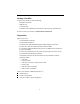
Installing the NAM into a Multislot Housing The illustration shows the 14-slot access carrier housing. CAUTION: Be sure that you install the NAM in the correct slot so that it mates with its matching I/O card. Otherwise, you could damage your card. Procedure 1. Remove the NAM from the shipping box. Handle only by the top and bottom edges to avoid damaging the card. 2. At the front of the carrier, align the NAM with the upper and lower tracks of the appropriate slot. 3.
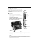
Connecting the COM Port to an Asynchronous Terminal A VT100-compatible asynchronous terminal or a PC providing VT100 terminal emulation must be used to set up access to and management of the unit. Procedure 1. Configure the VT100-compatible asynchronous terminal or PC to be compatible with the FrameSaver unit: — COM Port in use by your PC is COM1 or COM2. — COM Port Baud Rate is set to 19.2 Kbps. — Character length is set to 8 data bits. — Parity is set to None. — Stop bit is set to 1.
A Quick Guide to Configuration The FrameSaver unit should operate using the default (factory-set) configuration options, with exception to the changes specified in these installation instructions. Refer to the following table for help in navigating the menus. Press the . . . To . . . Esc key Go back one screen or menu level. To see a visual representation of the menu levels, see Menu Hierarchy in the Quick Reference.
About the Installation Procedures There are two methods for installing and setting up the FrameSaver unit. One person can install and set up the unit. If this is the case, see Full Installation and Setup. An installer can physically install and set up access to the unit, and the network operation center (NOC) can complete the setup. If this is the case, see Minimal Installation for Service Providers on page 11. Certain procedures are common to both the full installation and minimal methods.
It is assumed that frame relay service is turned on at the site. Procedure 1. Select the Easy Install feature. Main Menu → Easy Install 2. Enter the Node IP Address and Subnet Mask. 3. Set TS Access to DLCI, then select a DLCI on the network interface that will be used for the troubleshooting access link. 4.
11. Set up SNMP local management (see Setting Up Local Management at the Central Site on page 13). 12. Set up the modem, and the Call Directories if trap dial-out is desired (see Setting Up the Modem on page 14). 13. If the unit is equipped with an ISDN DBM, set up the DBM (see Setting Up the ISDN DBM on page 16). 14. If SNMP traps are wanted, set up managers, select the desired traps, and configure trap dial-out if desired (see Configuring SNMP Trap Managers and Trap Dial-Out on page 18). 15.
Minimal Installation for Service Providers In the following procedures, once the unit is installed and minimal configuration is completed using the Easy Install feature, the NOC can complete and verify the setup. Physically Installing the Unit and Setting Up for Remote Access It is assumed that frame relay service is turned on at the site. For a FrameSaver SLV 9128-II, this procedure is for setting up the unit in Frame Relay mode; the FrameSaver SLV 9128 is always in Frame Relay mode. Procedure 1.
Completing Setup of the Unit From the NOC Procedure 1. Access the remote FrameSaver unit using the dedicated management link, using the Node IP Address that was entered (see Physically Installing the Unit and Setting Up for Remote Access on page 11). 2. Configure specific frame relay options, like CIR (committed information rate), and any other configuration options requiring input or changes from the default settings. 3.
Setting Up Local Management at the Central Site Procedure 1. Create a DLCI for the data port. Configuration → Data Ports → DLCI Records 2. Save the configuration. 3. Create a Management PVC using the data port DLCI just created.
Automatic Configuration The FrameSaver unit provides several automatic configuration features. Frame Relay Discovery and configuration is one of these features. Main Menu → Auto-Configuration The default discovery mode is 1MPort. In this mode, for each DLCI discovered on the network, the unit creates a network interface DLCI containing two EDLCIs (embedded DLCIs – one for Port-1 data and the other for management), a Port-1 DLCI with the same number, and a management PVC, then cross-connects them.
Setting Up Call Directories if Trap Dial-Out Is Desired Procedure 1. Set up directory phone numbers. Main Menu → Control → Modem Call Directories 2. Select Directory Number A (for Alarm). 3. Enter the phone number(s). Valid characters include: — ASCII text — B for blind dialing — W for wait for dial tone — P for pulse dialing unless B specified — T for tone dialing unless B specified — Space, underscore ( _ ), comma (,) for a 2-second pause, and dash (–) readability characters 4.
Setting Up the ISDN DBM FrameSaver SLV 9128s and 9128-IIs may be equipped with an ISDN PRI DBM. These instructions are for units with ISDN backup capability. The following guidelines apply: Central site configuration guidelines: — Set up the ISDN DBM physical interface. — Modify the Link Profile(s) that Automatic Backup Configuration created to add a phone number. — Configure the unit to answer calls from the remote sites. (A PRI DBM is already configured to answer calls.
Modifying ISDN Link Profiles Procedure 1. Select Link Profiles, then Modify. The FrameSaver unit automatically configures an ISDN Link Profile on the first ISDN link, with HQ_Site as the Link Name. For subsequent ISDN Link Profiles, select New. 2. Add a name and phone number to the ISDN Link Profile(s) created by Automatic Backup Configuration. — Name for the destination entered (e.g., Tampa). The default setting is HQ_Site.
Configuring SNMP Trap Managers and Trap Dial-Out Once the FrameSaver unit is connected to the network, SNMP trap managers, SNMP traps, and trap dial-out can be configured. Procedure 1. Select SNMP Traps. Main Menu → Configuration → Management and Communication → SNMP Traps 2. Configure the following: — Enable SNMP Traps. — Identify the total Number of Trap Managers. — Specify the IP address of the NMS(s) to which traps will be sent. — Specify the network Destination for the Trap Manager(s).
Connecting to an M66 Block Use the optional T1 mass termination cable to connect up to seven NAMs to an M66 block. The T1 mass termination cable is a 5-foot RJ48H cable consisting of a 50-pin plug-to-seven RJ48C plugs. Plug Number Label Procedure 1. Insert RJ48C plugs on the RJ48H network cable into up to seven FrameSaver unit NET interface(s). 2. Insert the 50-pin plug end of the cable into the M66 block. M66 Block NAMs RJ48C Plugs 50-Pin Plug 3.
Verifying the End-to-End Path After installation of a remote site unit, run an IP Ping test to ping the NMS at the central site and verify that the entire path from the remote unit to the NMS is functioning. To run the IP Ping test, NMS trap managers must have been configured for the remote unit. One of those trap managers must be the central site NMS. Procedure 1. Select the IP Ping test. Main Menu → Test → IP Ping 2. Enter the IP Address of the device being pinged, then select Start.
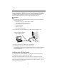
Connecting to ISDN Procedure 1. Insert the 8-pin connector on the ISDN cable into the DBM interface. RJ48C Jack SIN T1 GL NA E M N E T 1 D B M M D M DBM MDM D S X RJ11C Jack 2. Insert the other end of the cable into the ISDN service RJ48C jack. NET 1 E N E T 00-16838 Connecting the Modem Procedure 1. Insert the 6-pin connector on the modem cable into the MDM interface. 2. Insert the other end of the cable into the modem service RJ11C jack. Connecting to DSX Procedure 1.
Connecting to Ethernet Procedure 1. Insert one 8-pin connector of the Ethernet cable into the Ethernet port. 2. Insert the other end of the cable into the Ethernet interface of the LAN where the NMS resides. Connecting to a DTE Procedure SIN T1 GL NA E M N E T 1 1. Connect one end of the V.35 cable to Port 1 or Port 2. D B M M D M D S X 2. Connect the other end of the V.35 cable to the DTE.
Verifying Connections and Setup Check the modem, DSX, Ethernet, DTE, and PVC connections, as well as the ISDN DBM setup if a DBM is installed. Checking the Modem Connection Procedure If Port Use is set to Terminal (dial-in access): 1. Dial the modem’s phone number using a remote asynchronous terminal or PC. 2. Verify that the Main Menu appears. If Port Use is set to Net Link (SNMP, Telnet, FTP, and trap dial-out): 1. Dial the modem’s phone number using a PC running PPP or SLIP link protocol. 2.
Checking the DTE Connection Perform these checks for both user data ports. Procedure 1. Verify that the Port OK LED is on. If not, make sure both ends of the cable are properly seated and secured. Then, check the DTE; RTS or DTR could be down on the DTE. — The FrameSaver SLV 9128 has a Port OK LED for each port. — The FrameSaver SLV 9128-II has one Port OK LED for both ports. If either port is enabled and active, the LED is on. If both ports are enabled and one of the ports is inactive, the LED is off.
Checking PVC Connections Check PVC connections to verify that all PVCs, including management PVCs, are configured, and to see whether the PVC is active or not. Procedure 1. Press Esc to return to the Status menu. 2. Select PVC Connection Status. The PVC Connection Status screen shows all PVC connections; the interface and DLCI number of the source interface and DLCI number for the destination interface. You can also see whether the PVC is active. 3. Verify that each PVC is active.
Verifying the ISDN Line and That Data Can Be Passed Between DBMs Procedure 1. Verify the ISDN line by checking the DBM Interface Status. Main Menu → Status → DBM Interface Status Line Status should be Active. If an invalid (Inv) status is displayed, verify that you entered ISDN physical options correctly. 2. Check backup setup and that data can be passed between DBMs. — Select Test, then ISDN Call/PVC Tests Main Menu → Test → ISDN Call/PVC Tests — Select the link to be tested. — Start a Test Call.
! Important Safety Instructions 1. Read and follow all warning notices and instructions marked on the product or included in the manual. 2. If installed in a carrier with an AC power supply, this product is intended to be used with a 3-wire grounding type plug – a plug which has a grounding pin. This is a safety feature. Equipment grounding is vital to ensure safe operation. Do not defeat the purpose of the grounding type plug by modifying the plug or using an adapter.
7. General purpose cables are provided with this product. A UL Listed/CSA Certified, minimum No. 26 AWG, telecommunications cable is provided for connection to the network. Use this cable to reduce the risk of fire. Special cables, which may be required by the regulatory inspection authority for the installation site, are the responsibility of the customer. 8.
EMI Notices ! UNITED STATES – EMI NOTICE: This equipment has been tested and found to comply with the limits for a Class A digital device, pursuant to Part 15 of the FCC rules. These limits are designed to provide reasonable protection against harmful interference when the equipment is operated in a commercial environment.
If your unit causes harm to the telephone network, the telephone company may discontinue your service temporarily. If possible, they will notify you in advance. But if advance notice is not practical, you will be notified as soon as possible. You will be advised of your right to file a complaint with the FCC. Your telephone company may make changes in facilities, equipment, operations, or procedures that could affect the proper operation of your equipment.
Canada Notice to Users of the Canadian Telephone Network The Industry Canada label identifies certified equipment. This certification means that the equipment meets telecommunications network protective, operational and safety requirements as prescribed in the appropriate Terminal Equipment Technical Requirements document(s). The Department does not guarantee the equipment will operate to the user’s satisfaction.
Warranty, Sales, Service, and Training Information Contact your local sales representative, service representative, or distributor directly for any help needed. For additional information concerning warranty, sales, service, repair, installation, documentation, training, distributor locations, or Paradyne worldwide office locations, use one of the following methods: Internet: Visit the Paradyne World Wide Web site at www.paradyne.com. (Be sure to register your warranty at www.paradyne.com/warranty.