
Router User's Guide
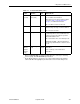

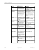

Table Of Contents
- Contents
- About This Guide
- 1. About the FrameSaver SLV
- 2. User Interface and Basic Operation
- 3. Configuration Procedures
- 4. Configuration Options
- Using the Easy Install Feature
- Using RIP with FrameSaver SLV CSU/DSUs
- Entering System Information and Setting the System Clock
- Setting Up the Modem
- Setting Up Auto-Configuration
- Setting Up Dial Backup
- PVC Backup Over the Network Interface
- Setting Up Back-to-Back Operation
- Configuration Option Tables
- Configuring the Overall System
- Configuring Physical Interfaces
- Assigning Time Slots/Cross Connections
- Configuring Frame Relay for an Interface
- Manually Configuring DLCI Records
- Configuring PVC Connections
- Configuring the IP Path List
- Setting Up Management and Communication Options
- Configuring the Criteria for Automatic Backup
- 5. Configuring the FrameSaver SLV Router
- FrameSaver SLV Router Overview
- IP Routing
- Address Resolution Protocol
- Proxy ARP
- Interface Configuration
- Network Address Translation
- Network Address Port Translation
- Dynamic Host Configuration Protocol Server
- DHCP Relay Agent
- Router Security
- Provisioning the Router Interface
- Configuring the Router Using Terminal Emulation
- 6. Security and Logins
- 7. Operation and Maintenance
- 8. Troubleshooting
- 9. Setting Up OpenLane for FrameSaver Devices and Activating SLM Features
- 10. Setting Up NetScout Manager Plus for FrameSaver Devices
- 11. Setting Up Network Health for FrameSaver Devices
- A. Menu Hierarchy
- B. SNMP MIBs and Traps, and RMON Alarm Defaults
- C. Router CLI Commands, Codes, and Designations
- D. Router Command Line Summaries and Shortcuts
- E. Connectors, Cables, and Pin Assignments
- F. Technical Specifications
- G. Equipment List
- Index
7. Operation and Maintenance
9128-A2-GB20-80 September 2002
7-11
Control Lead Descriptions
See Table 7-2, Network, DSX, or PRI Interface LEDs, for descriptions of these
leads. See Table 7-3, User Data Port LED (CSU/DSUs Only), to interpret the user
data port OK control lead. The LED descriptions and control lead descriptions are
the same.
In addition to these LEDs, additional control leads can be monitored through the
Display LEDs and Control Leads screen. These indicators show the current state
of each control lead and what they indicate when they are highlighted; that is, in
the On state. They are described in Table 7-5, Additional Control Leads.
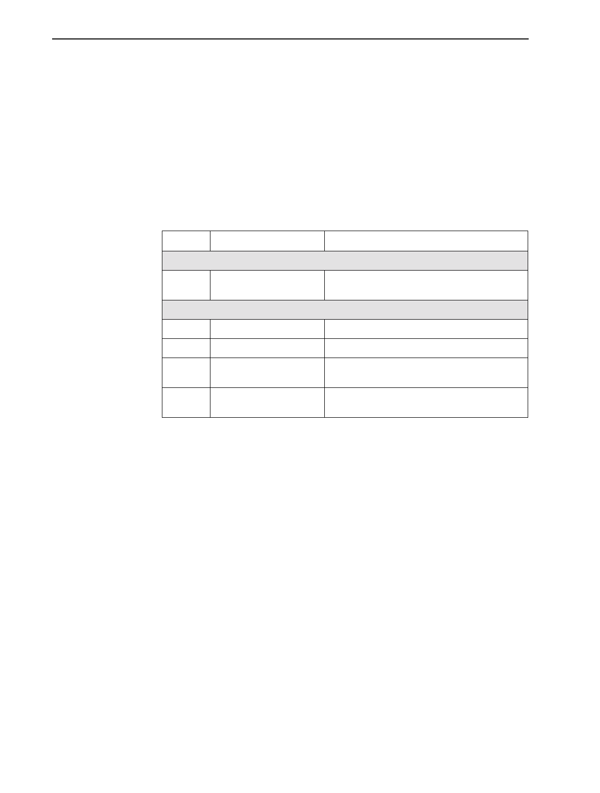
Table 7-5. Additional Control Leads
Label Indication What It Means
Network Interface
LMI OK LMI Operational Status LMI is operating successfully on the first frame
relay link on the network interface.
User Data Port
TXD Transmit Data Data is being sent to the far-end device.
RXD Receive Data Data is being received from the far-end device.
DTR Data Terminal Ready Shows the current state of the DTR control lead.
This indicator should always be on.
RTS Request to Send Shows the current state of the RTS control lead.
This indicator should always be on.