
Router User's Guide
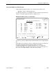
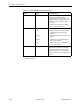
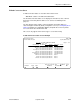
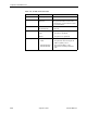

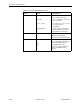
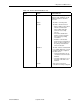
Table Of Contents
- Contents
- About This Guide
- 1. About the FrameSaver SLV
- 2. User Interface and Basic Operation
- 3. Configuration Procedures
- 4. Configuration Options
- Using the Easy Install Feature
- Using RIP with FrameSaver SLV CSU/DSUs
- Entering System Information and Setting the System Clock
- Setting Up the Modem
- Setting Up Auto-Configuration
- Setting Up Dial Backup
- PVC Backup Over the Network Interface
- Setting Up Back-to-Back Operation
- Configuration Option Tables
- Configuring the Overall System
- Configuring Physical Interfaces
- Assigning Time Slots/Cross Connections
- Configuring Frame Relay for an Interface
- Manually Configuring DLCI Records
- Configuring PVC Connections
- Configuring the IP Path List
- Setting Up Management and Communication Options
- Configuring the Criteria for Automatic Backup
- 5. Configuring the FrameSaver SLV Router
- FrameSaver SLV Router Overview
- IP Routing
- Address Resolution Protocol
- Proxy ARP
- Interface Configuration
- Network Address Translation
- Network Address Port Translation
- Dynamic Host Configuration Protocol Server
- DHCP Relay Agent
- Router Security
- Provisioning the Router Interface
- Configuring the Router Using Terminal Emulation
- 6. Security and Logins
- 7. Operation and Maintenance
- 8. Troubleshooting
- 9. Setting Up OpenLane for FrameSaver Devices and Activating SLM Features
- 10. Setting Up NetScout Manager Plus for FrameSaver Devices
- 11. Setting Up Network Health for FrameSaver Devices
- A. Menu Hierarchy
- B. SNMP MIBs and Traps, and RMON Alarm Defaults
- C. Router CLI Commands, Codes, and Designations
- D. Router Command Line Summaries and Shortcuts
- E. Connectors, Cables, and Pin Assignments
- F. Technical Specifications
- G. Equipment List
- Index
7. Operation and Maintenance
9128-A2-GB20-80 September 2002
7-35
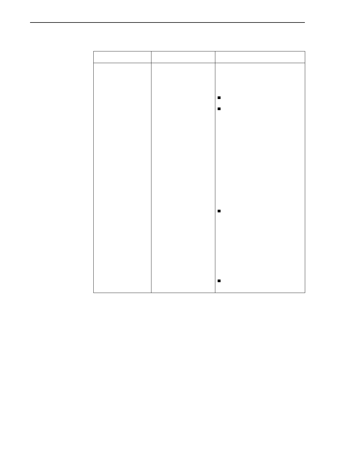
Status Identifies whether the physical
interfaces, LMIs, and DLCIs are all
enabled and active for this PVC
connection.
Active*
The PVC is currently active.
Inactive
The PVC is inactive because:
– Alarm conditions and network
and SLV communication
status indicate that data
cannot be successfully
passed.
– The unit has disabled the
interface or frame relay link
due to internal operating
conventions.
– Activation of an alternate
virtual circuit is not warranted;
that is, no alarm condition on
the primary destination link
has been detected.
Disabled
The PVC cannot be activated and
is essentially disabled as a result
of how the unit was configured.
Possible causes:
– The physical interface at one
or both ends of the PVC is/are
disabled.
– The frame relay link on one or
both ends of the PVC is/are
disabled.
Invalid
Some portion of the PVC
connection is not fully configured.
* For the circuit to be active, both Source and Destination Statuses must be Active.
Table 7-12. PVC Connection Status (2 of 2)
Field Status What It Indicates