
Router User's Guide
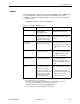
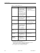
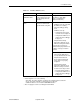
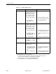
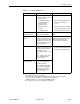
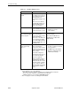
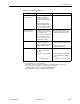
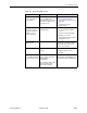
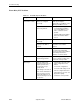
Table Of Contents
- Contents
- About This Guide
- 1. About the FrameSaver SLV
- 2. User Interface and Basic Operation
- 3. Configuration Procedures
- 4. Configuration Options
- Using the Easy Install Feature
- Using RIP with FrameSaver SLV CSU/DSUs
- Entering System Information and Setting the System Clock
- Setting Up the Modem
- Setting Up Auto-Configuration
- Setting Up Dial Backup
- PVC Backup Over the Network Interface
- Setting Up Back-to-Back Operation
- Configuration Option Tables
- Configuring the Overall System
- Configuring Physical Interfaces
- Assigning Time Slots/Cross Connections
- Configuring Frame Relay for an Interface
- Manually Configuring DLCI Records
- Configuring PVC Connections
- Configuring the IP Path List
- Setting Up Management and Communication Options
- Configuring the Criteria for Automatic Backup
- 5. Configuring the FrameSaver SLV Router
- FrameSaver SLV Router Overview
- IP Routing
- Address Resolution Protocol
- Proxy ARP
- Interface Configuration
- Network Address Translation
- Network Address Port Translation
- Dynamic Host Configuration Protocol Server
- DHCP Relay Agent
- Router Security
- Provisioning the Router Interface
- Configuring the Router Using Terminal Emulation
- 6. Security and Logins
- 7. Operation and Maintenance
- 8. Troubleshooting
- 9. Setting Up OpenLane for FrameSaver Devices and Activating SLM Features
- 10. Setting Up NetScout Manager Plus for FrameSaver Devices
- 11. Setting Up Network Health for FrameSaver Devices
- A. Menu Hierarchy
- B. SNMP MIBs and Traps, and RMON Alarm Defaults
- C. Router CLI Commands, Codes, and Designations
- D. Router Command Line Summaries and Shortcuts
- E. Connectors, Cables, and Pin Assignments
- F. Technical Specifications
- G. Equipment List
- Index
8. Troubleshooting
9128-A2-GB20-80 September 2002
8-11
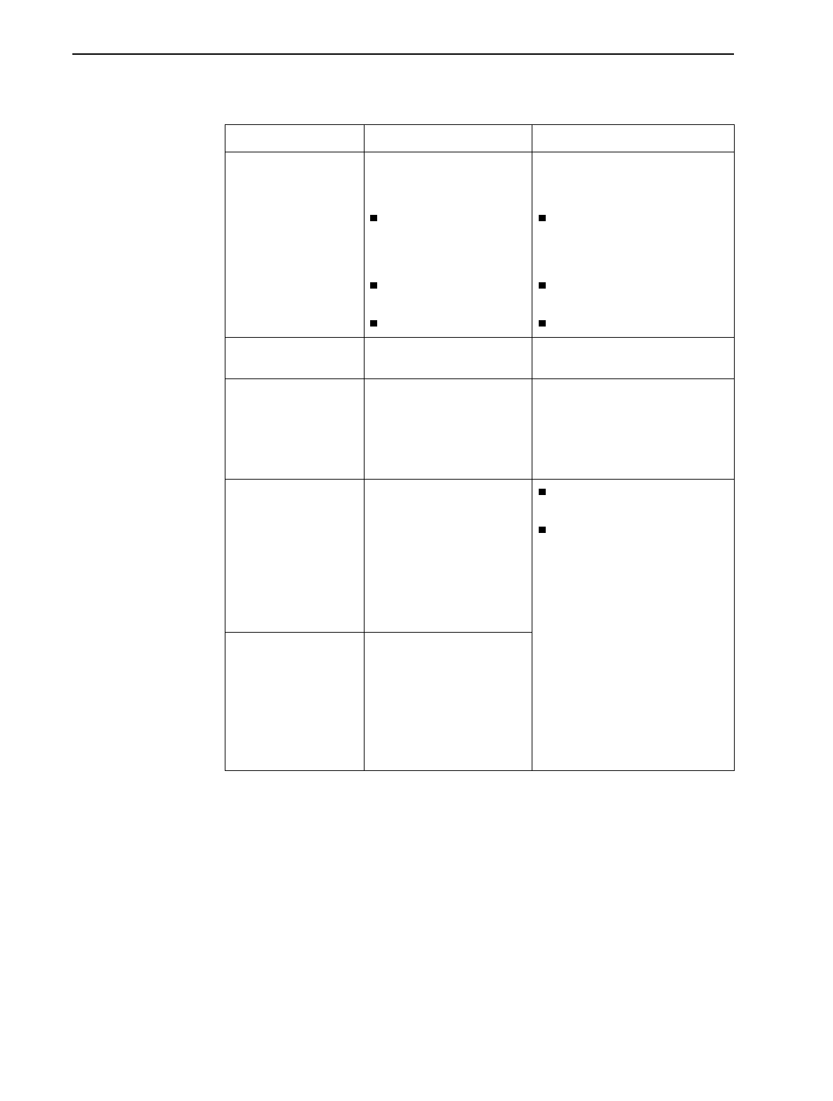
OOF at Network 1 An Out of Frame (OOF)
condition is detected on the
network interface.
Incompatible framing
format between the
network and the
FrameSaver unit.
Network cabling
problem.
T1 facility problem.
Check that the framing format
for the network interface is
correct.
Check that the network cable is
securely attached at both ends.
Contact your network provider.
Path
IP_ Address
Down, DLCI
nnnn
1
A path on the network
interface is unavailable.
Determine why the path went
down.
Power Supply/Fan
Alarm
The power supply output
voltage has dropped below
the specified tolerance level
required for the system. Or
one or both fan trays are not
operating properly.
Check the LEDs on the power
supply and fan trays to determine
which may have failed, then
replace the failed component.
Primary Clock Failed A failure of the configured
primary clock source for the
unit was detected and the
secondary clock is
providing the timing for the
unit.
This condition clears when
the configured primary
clock is restored.
Check that the network cable is
securely attached at both ends.
Contact your network provider.
Primary & Secondary
Clocks Failed
A failure of both clock
sources configured for the
unit was detected.
This condition only applies
to T1 network and DSX-1
interfaces. It clears when
the configured primary
clock is restored.
Table 8-1. Alarm Conditions (5 of 7)
Alarm Condition What It Indicates What To Do
1
nnnn
indicates a DLCI number of 16 through 1007.
2
frame relay link
is one of the following:
– Net1-FR1. The frame relay link specified for the network interface, Network 1.
– Port-
n
. The frame relay link associated with a user data port.
–
ISDN Link Name
on a non-network ISDN DBM interface.
3
Does not apply to a TS Access Management Link DLCI.