
Router User's Guide

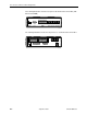
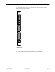
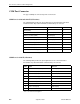
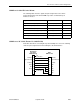
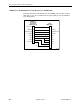
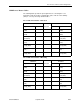
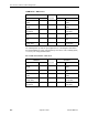
Table Of Contents
- Contents
- About This Guide
- 1. About the FrameSaver SLV
- 2. User Interface and Basic Operation
- 3. Configuration Procedures
- 4. Configuration Options
- Using the Easy Install Feature
- Using RIP with FrameSaver SLV CSU/DSUs
- Entering System Information and Setting the System Clock
- Setting Up the Modem
- Setting Up Auto-Configuration
- Setting Up Dial Backup
- PVC Backup Over the Network Interface
- Setting Up Back-to-Back Operation
- Configuration Option Tables
- Configuring the Overall System
- Configuring Physical Interfaces
- Assigning Time Slots/Cross Connections
- Configuring Frame Relay for an Interface
- Manually Configuring DLCI Records
- Configuring PVC Connections
- Configuring the IP Path List
- Setting Up Management and Communication Options
- Configuring the Criteria for Automatic Backup
- 5. Configuring the FrameSaver SLV Router
- FrameSaver SLV Router Overview
- IP Routing
- Address Resolution Protocol
- Proxy ARP
- Interface Configuration
- Network Address Translation
- Network Address Port Translation
- Dynamic Host Configuration Protocol Server
- DHCP Relay Agent
- Router Security
- Provisioning the Router Interface
- Configuring the Router Using Terminal Emulation
- 6. Security and Logins
- 7. Operation and Maintenance
- 8. Troubleshooting
- 9. Setting Up OpenLane for FrameSaver Devices and Activating SLM Features
- 10. Setting Up NetScout Manager Plus for FrameSaver Devices
- 11. Setting Up Network Health for FrameSaver Devices
- A. Menu Hierarchy
- B. SNMP MIBs and Traps, and RMON Alarm Defaults
- C. Router CLI Commands, Codes, and Designations
- D. Router Command Line Summaries and Shortcuts
- E. Connectors, Cables, and Pin Assignments
- F. Technical Specifications
- G. Equipment List
- Index
E. Connectors, Cables, and Pin Assignments
9128-A2-GB20-80 September 2002
E-5
COM Port for 9128-II Carrier Mount
The following table shows the signals and pin assignments for the carrier-
mounted FrameSaver SLV 9128-II NAM’s 8-position communication port
interface/connector.
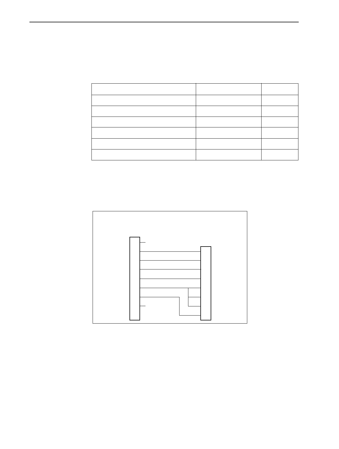
COM Port-to-PC Cable (Feature No. 3100-F2-550)
Order this cable when connecting the 8-position COM port to a PC. The following
shows the pin assignments from the COM port to the DTE interface.
Signal Direction Pin #
DCE Received Data (RXD) From DCE (Out) 2
Signal Ground (SG) To/From DCE 3
DCE Transmit Data (TXD) To DCE (In) 4
DCE Data Terminal Ready (DTR) To DCE (In) 5
DCE Carrier Detect (CD) From DCE (Out) 6
DCE Request to Send (RTS) To DCE (In) 7
1
2
3
4
5
6
7
8
98-16166
COM Port
Non-Keyed
8-Position
Modular Plug
Tx Clock
Rx Data
Signal Ground
Tx Data
DTR
CD
RTS
Rx Clock
2
5
3
4
1
8
6
7
Rx Data
Signal Ground
Tx Data
DTR
CD
CTS
DSR
RTS
DTE
DB9 Socket
No
Connection
No
Connection