
Manual
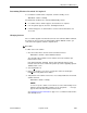
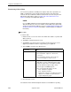

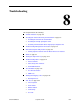
Table Of Contents
- Contents
- About This Guide
- 1. About the FrameSaver SLV
- 2. User Interface and Basic Operation
- 3. Configuration Procedures
- 4. Configuration Options
- Using the Easy Install Feature
- Using RIP with FrameSaver SLV CSU/DSUs
- Entering System Information and Setting the System Clock
- Setting Up the Modem
- Setting Up Auto-Configuration
- Setting Up Dial Backup
- PVC Backup Over the Network Interface
- Setting Up Back-to-Back Operation
- Configuration Option Tables
- Configuring the Overall System
- Configuring Physical Interfaces
- Assigning Time Slots/Cross Connections
- Configuring Frame Relay for an Interface
- Manually Configuring DLCI Records
- Configuring PVC Connections
- Configuring the IP Path List
- Setting Up Management and Communication Options
- Configuring the Criteria for Automatic Backup
- 5. Configuring the FrameSaver SLV Router
- FrameSaver SLV Router Overview
- IP Routing
- Address Resolution Protocol
- Proxy ARP
- Interface Configuration
- Network Address Translation
- Network Address Port Translation
- Dynamic Host Configuration Protocol Server
- DHCP Relay Agent
- Router Security
- Provisioning the Router Interface
- Configuring the Router Using Terminal Emulation
- 6. Security and Logins
- 7. Operation and Maintenance
- 8. Troubleshooting
- 9. Setting Up OpenLane for FrameSaver Devices and Activating SLM Features
- 10. Setting Up NetScout Manager Plus for FrameSaver Devices
- 11. Setting Up Network Health for FrameSaver Devices
- A. Menu Hierarchy
- B. SNMP MIBs and Traps, and RMON Alarm Defaults
- C. Router CLI Commands, Codes, and Designations
- D. Router Command Line Summaries and Shortcuts
- E. Connectors, Cables, and Pin Assignments
- F. Technical Specifications
- G. Equipment List
- Index

8. Troubleshooting
8-2
September 2002 9128-A2-GB20-80
Physical Tests
on page 8-26
—
Line Loopback
—
Payload Loopback
—
Repeater Loopback
—
DTE Loopback
—
Send Line Loopback
—
Data Channel Loopbacks on a Frame Relay Link
—
Send Remote Line Loopback
—
Send and Monitor Pattern Tests
IP Ping Test
on page 8-35
Lamp Test
on page 8-40
Problem Indicators
The unit provides a number of indicators to alert you to possible problems:
Indicators . . . See . . .
LEDs
Viewing LEDs and Control Leads
and
LED Descriptions
in
Chapter 7,
Operation and Maintenance
, as well as the user
interface screen.
Main Menu
→
Status
→
Display LEDs and Control LEDs
Health and Status Table 7-8, Health and Status Messages, in Chapter 7,
Operation and Maintenance
.
Main Menu
→
Status
→
System and Test Status
Messages also appear at the bottom of any menu-driven
user interface screen.
Performance statistics
Performance Statistics
in Chapter 7,
Operation and
Maintenance
, to help you determine how long a problem
has existed.
Alarm conditions that will
generate an SNMP trap
Alarms
on page 8-7.
SNMP traps Appendix B,
SNMP MIBs and Traps, and RMON Alarm
Defaults.
Traps supported include warm-start, authentication-failure,
enterprise-specific (those specific to the unit), link-up, and
link-down.