
Manual
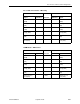
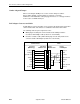
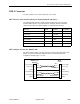
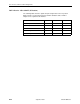
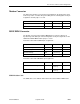
Table Of Contents
- Contents
- About This Guide
- 1. About the FrameSaver SLV
- 2. User Interface and Basic Operation
- 3. Configuration Procedures
- 4. Configuration Options
- Using the Easy Install Feature
- Using RIP with FrameSaver SLV CSU/DSUs
- Entering System Information and Setting the System Clock
- Setting Up the Modem
- Setting Up Auto-Configuration
- Setting Up Dial Backup
- PVC Backup Over the Network Interface
- Setting Up Back-to-Back Operation
- Configuration Option Tables
- Configuring the Overall System
- Configuring Physical Interfaces
- Assigning Time Slots/Cross Connections
- Configuring Frame Relay for an Interface
- Manually Configuring DLCI Records
- Configuring PVC Connections
- Configuring the IP Path List
- Setting Up Management and Communication Options
- Configuring the Criteria for Automatic Backup
- 5. Configuring the FrameSaver SLV Router
- FrameSaver SLV Router Overview
- IP Routing
- Address Resolution Protocol
- Proxy ARP
- Interface Configuration
- Network Address Translation
- Network Address Port Translation
- Dynamic Host Configuration Protocol Server
- DHCP Relay Agent
- Router Security
- Provisioning the Router Interface
- Configuring the Router Using Terminal Emulation
- 6. Security and Logins
- 7. Operation and Maintenance
- 8. Troubleshooting
- 9. Setting Up OpenLane for FrameSaver Devices and Activating SLM Features
- 10. Setting Up NetScout Manager Plus for FrameSaver Devices
- 11. Setting Up Network Health for FrameSaver Devices
- A. Menu Hierarchy
- B. SNMP MIBs and Traps, and RMON Alarm Defaults
- C. Router CLI Commands, Codes, and Designations
- D. Router Command Line Summaries and Shortcuts
- E. Connectors, Cables, and Pin Assignments
- F. Technical Specifications
- G. Equipment List
- Index

E. Connectors, Cables, and Pin Assignments
9128-A2-GB20-80 September 2002
E-9
Cisco 7000 Series Router – DB25 Plug
3COM Router – DB9 Socket
COM Port
Direction
AUX Port
Signal RJ45 Pin # DB25 Pin # Signal
DCE Receive Data
(RXD)
2 From DTE 3 DTE Receive Data
(RXD)
DCE Signal Ground
(SG)
3 — 7 DTE Signal Ground
(SG)
DCE Transmit Data
(TXD)
4 To DTE 2 DTE Transmit Data
(TXD)
DCE Data Terminal
Ready (DTR)
5 To DTE 20 DTE Data Terminal
Ready (DTR)
DCE Carrier Detect
(CD)
6 To DTE 8 DTE Carrier Detect
(CD)
DCE Request to
Send (RTS)
7 To DTE 4 DTE Request to
Send (RTS)
COM Port
Direction
AUX Port
Signal RJ45 Pin # DB25 Pin # Signal
DCE Receive Data
(RXD)
2 From DTE 2 DTE Receive Data
(RXD)
DCE Signal Ground
(SG)
3 — 5 DTE Signal Ground
(SG)
DCE Transmit Data
(TXD)
4 To DTE 3 DTE Transmit Data
(TXD)
DCE Data Terminal
Ready (DTR)
5 To DTE 4 DTE Data Terminal
Ready (DTR)
DCE Carrier Detect
(CD)
6 To DTE 1 DTE Carrier Detect
(CD)
DCE Request to
Send (RTS)
7 To DTE 7 DTE Request to
Send (RTS)