
Manual
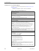
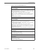
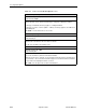
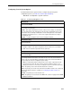
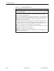
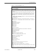
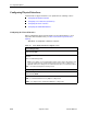
Table Of Contents
- Contents
- About This Guide
- 1. About the FrameSaver SLV
- 2. User Interface and Basic Operation
- 3. Configuration Procedures
- 4. Configuration Options
- Using the Easy Install Feature
- Using RIP with FrameSaver SLV CSU/DSUs
- Entering System Information and Setting the System Clock
- Setting Up the Modem
- Setting Up Auto-Configuration
- Setting Up Dial Backup
- PVC Backup Over the Network Interface
- Setting Up Back-to-Back Operation
- Configuration Option Tables
- Configuring the Overall System
- Configuring Physical Interfaces
- Assigning Time Slots/Cross Connections
- Configuring Frame Relay for an Interface
- Manually Configuring DLCI Records
- Configuring PVC Connections
- Configuring the IP Path List
- Setting Up Management and Communication Options
- Configuring the Criteria for Automatic Backup
- 5. Configuring the FrameSaver SLV Router
- FrameSaver SLV Router Overview
- IP Routing
- Address Resolution Protocol
- Proxy ARP
- Interface Configuration
- Network Address Translation
- Network Address Port Translation
- Dynamic Host Configuration Protocol Server
- DHCP Relay Agent
- Router Security
- Provisioning the Router Interface
- Configuring the Router Using Terminal Emulation
- 6. Security and Logins
- 7. Operation and Maintenance
- 8. Troubleshooting
- 9. Setting Up OpenLane for FrameSaver Devices and Activating SLM Features
- 10. Setting Up NetScout Manager Plus for FrameSaver Devices
- 11. Setting Up Network Health for FrameSaver Devices
- A. Menu Hierarchy
- B. SNMP MIBs and Traps, and RMON Alarm Defaults
- C. Router CLI Commands, Codes, and Designations
- D. Router Command Line Summaries and Shortcuts
- E. Connectors, Cables, and Pin Assignments
- F. Technical Specifications
- G. Equipment List
- Index

4. Configuration Options
4-28
September 2002 9128-A2-GB20-80
Configuring Service
Level Verification Options
SLV options are selected from the System menu (see Table 4-4, Service Level
Verification Options).
Main Menu
→
Configuration
→
System
→
Service Level Verification
Table 4-4. Service Level Verification Options (1 of 3)
SLV Sample Interval (secs)
Possible Settings:
10 – 3600
Default Setting:
60
Sets the inband communications interval between FrameSaver SLV devices. Inband
communications are used to pass frames that calculate latency, as well as transmission
success and other SLV information.
10 – 3600
– Sets the SLV Sample Interval (secs) in seconds.
SLV Synchronization Role
Available Settings:
Tributary, Controller, None
Default Setting:
Tributary
Determines the role the unit plays in maintaining synchronization of user history data
collection and storage between FrameSaver SLV and/or FLEX devices.
Tributary
– Uses network timing received from incoming SLV communications and
provides network-based synchronization information to other devices in the network.
Controller
– Uses its own internal time-of-day clock and provides synchronization
information to other devices in the network based upon its own clock.
NOTE: Only one device in the network should be configured as the SLV
synchronization controller.
None
– Incoming timing information is ignored and no timing information is sent out. This
setting should only be used when network synchronization is not desirable, or when a
single unit connects multiple networks or network segments.
SLV Type
Available Settings:
Standard, COS 1–COS 7
Default Setting:
If SLV Feature is enabled:
Standard
If SLV Feature is disabled:
COS 1
Determines the type of SLV measurements to which these other SLV options apply:
SLV Timeout Error Event Threshold
SLV Timeout Clearing Event Threshold
SLV Round Trip Latency Error Threshold
SLV Latency Clearing Event Threshold
SLV Packet Size
Standard
– The options selected apply to standard FrameSaver SLV measurements,
utlizing an EDLCI for FrameSaver-to-FrameSaver communication. This option is not
available if the SLV Feature is disabed.
COS 1–COS 7
– The options selected apply to this Class of Service. Different settings
may be saved for each Class of Service.