FrameSaver DSL 9783 USER’S GUIDE Document No.
Copyright E 2000 Paradyne Corporation All rights reserved. Printed in U.S.A. Notice This publication is protected by federal copyright law. No part of this publication may be copied or distributed, transmitted, transcribed, stored in a retrieval system, or translated into any human or computer language in any form or by any means, electronic, mechanical, magnetic, manual or otherwise, or disclosed to third parties without the express written permission of Paradyne Corporation, 8545 126th Ave. N.
Contents About This Guide H H H H 1 Purpose and Intended Audience . . . . . . . . . . . . . . . . . . . . . . . . . . . . . . . . . . Document Organization . . . . . . . . . . . . . . . . . . . . . . . . . . . . . . . . . . . . . . . . . . Product-Related Documents . . . . . . . . . . . . . . . . . . . . . . . . . . . . . . . . . . . . . . Conventions Used . . . . . . . . . . . . . . . . . . . . . . . . . . . . . . . . . . . . . . . . . . . . . . About the FrameSaver DSL Unit H System Overview . . . . .
Contents 4 Configuration Options H H H H H H H H H H H H 5 4-1 4-3 4-6 4-6 4-7 4-7 4-8 4-10 4-12 4-13 4-13 4-14 4-16 4-18 4-19 4-22 4-24 4-24 4-28 4-31 4-33 4-36 4-37 4-40 4-42 4-46 Security and Logins H H H H H H H H ii Overview . . . . . . . . . . . . . . . . . . . . . . . . . . . . . . . . . . . . . . . . . . . . . . . . . . . . . . Using the Easy Install Feature . . . . . . . . . . . . . . . . . . . . . . . . . . . . . . . . . . . . Setting Up So the Router Can Receive RIP . . . . . . . . . .
Contents 6 Operation and Maintenance H Displaying System Information . . . . . . . . . . . . . . . . . . . . . . . . . . . . . . . . . . . . H Viewing LEDs and Control Leads . . . . . . . . . . . . . . . . . . . . . . . . . . . . . . . . . LED Descriptions . . . . . . . . . . . . . . . . . . . . . . . . . . . . . . . . . . . . . . . . . . . . Control Lead Descriptions . . . . . . . . . . . . . . . . . . . . . . . . . . . . . . . . . . . . H Device Messages . . . . . . . . . . . . . . . . . . . . . . . . .
Contents 8 Troubleshooting H Problem Indicators . . . . . . . . . . . . . . . . . . . . . . . . . . . . . . . . . . . . . . . . . . . . . . H Resetting the Unit and Restoring Communication . . . . . . . . . . . . . . . . . . . Resetting the Unit from the Control Menu . . . . . . . . . . . . . . . . . . . . . . . Resetting the Unit By Cycling the Power . . . . . . . . . . . . . . . . . . . . . . . . Restoring Communication with an Improperly Configured Unit . . . . .
Contents 10 Setting Up Network Health for FrameSaver Devices H H H H H Installation and Setup of Network Health . . . . . . . . . . . . . . . . . . . . . . . . . . . Discovering FrameSaver Elements . . . . . . . . . . . . . . . . . . . . . . . . . . . . . . . . Configuring the Discovered Elements . . . . . . . . . . . . . . . . . . . . . . . . . . . . . . Grouping Elements for Reports . . . . . . . . . . . . . . . . . . . . . . . . . . . . . . . . . . . Generating Reports for a Group . . . . . . . . . . .
Contents C Connectors, Cables, and Pin Assignments H Rear Panel . . . . . . . . . . . . . . . . . . . . . . . . . . . . . . . . . . . . . . . . . . . . . . . . . . . . . H DSL Network Interface Cable . . . . . . . . . . . . . . . . . . . . . . . . . . . . . . . . . . . . . H COM Port Connector . . . . . . . . . . . . . . . . . . . . . . . . . . . . . . . . . . . . . . . . . . . . Standard EIA-232-D Crossover Cable . . . . . . . . . . . . . . . . . . . . . . . . . . H Data Port Connector . . . . . . . . .
About This Guide Purpose and Intended Audience This document contains information that applies to the FrameSaver DSL 9783. It is intended for system designers, engineers, administrators, and operators who are familiar with the functional operation of digital data communications equipment and frame relay networks. Document Organization 9783-A2-GB20-00 Section Description Chapter 1 About the FrameSaver DSL Unit.
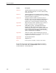
About This Guide Section Description Chapter 8 Troubleshooting. Provides device problem resolution, alarm, and other information, as well as troubleshooting and test procedures. Chapter 9 Setting Up OpenLane for FrameSaver Devices. Identifies where installation and setup information is located and how FrameSaver units are supported. Chapter 10 Setting Up Network Health for FrameSaver Devices.
About This Guide Product-Related Documents Document Number Document Title Paradyne FrameSaver Documentation: 9000-A2-GB20 Configuring Frame Relay Service Over DSL 9783-A2-GN10 FrameSaver DSL 9783 Installation Instructions 9783-A2-GL10 FrameSaver DSL 9783 Quick Reference Paradyne Hotwire Documentation: 8335-A2-GB20 Hotwire ATM Line Cards, Models 8335 and 8365, User’s Guide 8820-A2-GN20 Hotwire 8820 GranDSLAM Installation Guide Paradyne OpenLane NMS Documentation: 7800-A2-GZ41 OpenLane 5.
About This Guide Conventions Used Convention Used When Used Italic To indicate variable information (e.g., DLCI nnnn). Menu selection sequence To provide an abbreviated method for indicating the selections to be made from a menu or selections from within a menu before performing a procedural step. For example, Main Menu → Status → System and Test Status indicates that you should select Status from the Main Menu, then select System and Test Status from the Status menu).
About the FrameSaver DSL Unit 1 This chapter includes the following: H System Overview H FrameSaver DSL Features and Benefits H FrameSaver DSL Feature Sets — Basic Features — Advanced SLV Features H OpenLane SLM System System Overview Our system solution consists of: H FrameSaverr DSL (Digital Subscriber Line) unit H Hotwirer ATM Line Card in the Hotwire 8820 GranDSLAM H OpenLanet SLM (Service Level Management) system This solution provides increased manageability, monitoring, and diagnostics
About the FrameSaver DSL Unit FrameSaver DSL Features and Benefits Large-scale deployment of frame relay services over DSL-based access networks is possible with the innovative FrameSaver DSL, which provides important advantages for frame relay service providers. H Remote diagnostic and service level management (SLM) functionality allows service providers to install the unit and verify operation quickly and reliably.
About the FrameSaver DSL Unit H Advanced SLM and reporting feature set includes all of the diagnostic feature set, plus: — CIR relationship statistics — FDR/DDR (Trueput) reporting — Continuous real-time latency report — RMON2 alarms and proactive thresholds — FTP user history poller for graphical and historical reporting H Performs FRF.
About the FrameSaver DSL Unit An advanced SLM and reporting feature set can be activated on command with the SLV key. In the base configuration, comprehensive Layer 1 and 2 instrumentation allows service providers to isolate, diagnose, and correct problems remotely from their NOC. FR NSPs can expect fewer truck rolls and faster service turn-up times.
About the FrameSaver DSL Unit The following diagram shows the FrameSaver DSL unit in a frame relay network.
About the FrameSaver DSL Unit FrameSaver DSL Feature Sets Depending upon the model ordered, the FrameSaver DSL unit has the basic FrameSaver frame relay and diagnostic capability, or it is enhanced with additional SLV (Service Level Verification) reporting capability. These are referred to as feature sets, which provide different levels of intelligence for monitoring, managing, and reporting performance of the unit. The two feature sets include: H Basic Feature Set.
About the FrameSaver DSL Unit To obtain an activation certificate, provide the model number (9783), your OpenLane system license key number, and the number of FrameSaver units whose SLV capability is to be activated. When you receive your certificate, it will include an Activation Certificate number, the Feature Group Number for the additional SLV features (Feature Group 2), your OpenLane license key number, and the number of device activations (license keys) ordered.
About the FrameSaver DSL Unit Basic Features The FrameSaver DSL unit provides the following features: H Easy Installation. When AutoBaud is used, no configuration is required. SNMP options may be modified if desired to provide security and enable traps. H Frame Relay Aware Management. Supports diagnostic and network management features over the frame relay network. The unit’s frame relay capability also supports: — Inband management channels over the frame relay network using dedicated PVCs.
About the FrameSaver DSL Unit H Dual Flash Memory. Allows software upgrades while the unit is up and running. Two software loads can be stored and implemented at the user’s discretion. H Multiplexed Management PVCs. Provides a method of multiplexing management data with customer data transparently over a single PVC (Permanent Virtual Circuit) when FrameSaver devices are at each end of the circuit. This feature also makes it possible to run nondisruptive PVC tests.
About the FrameSaver DSL Unit H LMI Packet Capture. Provides a way of uploading data that has been captured in a trace file so the data can be uploaded and transferred to a Network Associates Sniffer for analysis, or viewed via the menu-driven user interface. When viewed from the menu-driven user interface, the 12 most recent LMI messages are displayed. Advanced SLV Features The following additional features are provided with the advanced SLV feature set: H TruePutt Technology.
About the FrameSaver DSL Unit OpenLane SLM System Being standards-based, the OpenLane SLM (Service Level Management) system can be used with other management applications like HP OpenView or IBM’s NetView. OpenLane includes HP OpenView adapters for integrating OpenLane features with the OpenView Web interface. Being Web-based, the OpenLane system provides Web access to the data contained in the database to provide anytime, anywhere access to this information via a Web browser.
About the FrameSaver DSL Unit 1-12 July 2000 9783-A2-GB20-00
User Interface and Basic Operation 2 This chapter explains how to access, use, and navigate the menu-driven user interface. It includes the following: H Logging On H Main Menu H Screen Work Areas H Navigating the Screens — Keyboard Keys — Function Keys — Selecting from a Menu — Switching Between Screen Areas — Selecting a Field — Entering Information What appears on the screens depends on: 9783-A2-GB20-00 H Current configuration – How your network is currently configured.
User Interface and Basic Operation Logging On Start a session using one of the following methods: H Telnet session via: — An in-band management channel through the frame relay network (frame relay network service provider). — An in-band management channel through the ATM network (DSL provider). — A local in-band management channel configured on the DTE port between the FrameSaver unit and the router. — A LAN port. H Dial-in connection using an external modem.
User Interface and Basic Operation If your login was . . . Then the . . . Valid Main Menu appears. Begin your session. NOTE: If your login is valid, but access is denied, there are two currently active sessions. Invalid Message, Invalid Password, appears on line 24, and the Login screen is redisplayed. After three unsuccessful attempts: H A Telnet session is closed. H The User Interface Idle screen appears for a directly connected terminal or modem. H An SNMP trap is generated. H Access is denied.
User Interface and Basic Operation Main Menu Entry to all of the FrameSaver unit’s tasks begins at the Main Menu, which has six menus or branches. The Access Level at the top of the screen only appears when security has been set up.
User Interface and Basic Operation Screen Work Areas There are two user work areas: H Screen area – Where you input information into fields. H Function keys area – Where you perform specific screen functions.
User Interface and Basic Operation Navigating the Screens You can navigate the screens by: H Using keyboard keys. H Switching between the two screen work areas using function keys. Keyboard Keys Use the following keyboard keys to navigate within the screen area: 2-6 Press . . . To . . . Ctrl-a Move cursor between the screen area and the screen function keys area. Esc Return to the previous screen. Right Arrow (on same screen row), or Tab (on any screen row) Move cursor to the next field.
User Interface and Basic Operation Function Keys All function keys (located in the lower part of the screen; see the example in Screen Work Areas on page 2-5) operate the same way throughout the screens. They are not case-sensitive, so upper- or lowercase letters can be used interchangeably. These keys use the following conventions: Select . . . For the screen And press Enter to . . . function . . . M or m MainMenu Return to the Main Menu screen.
User Interface and Basic Operation Selecting from a Menu " Procedure To select from a menu: 1. Tab or press the down arrow key to position the cursor on a menu selection, or press the up arrow key to move the cursor to the bottom of the menu list. Each menu selection is highlighted as you press the key to move the cursor from position to position. 2. Press Enter. The selected menu or screen appears. " Procedure To return to a previous screen, press the Escape (Esc) key until you reach the desired screen.
User Interface and Basic Operation Selecting a Field Once you reach the desired menu or screen, select a field to view or change, or issue a command. Press the Tab or right arrow key to move the cursor from one field to another. The current setting or value appears to the right of the field. Entering Information You can enter information in one of three ways. Select the field, then: H Manually type in (enter) the field value or command.
User Interface and Basic Operation This page intentionally left blank.
Configuration Procedures 3 This chapter includes the following: H Basic Configuration — Configuration Option Areas — Accessing and Displaying Configuration Options — Changing Configuration Options — Saving Configuration Options 9783-A2-GB20-00 July 2000 3-1
Configuration Procedures Basic Configuration Configuration option settings determine how the FrameSaver DSL Unit operates. Use the unit’s Configuration Edit/Display menu to display or change configuration option settings. The Configuration Edit/Display menu of the FrameSaver DSL Unit is shown below.
Configuration Procedures Configuration Option Areas The FrameSaver unit arrives with configured factory default settings, which are located in the Factory Default Configuration option area.
Configuration Procedures Accessing and Displaying Configuration Options To access and display configuration options, load (copy) the applicable configuration option set into the edit area. " Procedure To load a set of configuration options for editing: 1. From the Main Menu, press the down arrow key so the cursor is on Configuration. 2. Press Enter to display the Configuration menu. The Load Configuration From: menu appears.
Configuration Procedures Changing Configuration Options " Procedure To change configuration option settings: 1. From the Configuration Edit/Display menu, select a set of configuration options and press Enter. For example: Configuration → PVC Connections 2. Select the configuration options that are applicable to your network, and make appropriate changes to the setting(s). See Chapter 2, User Interface and Basic Operation, for additional information.
Configuration Procedures Saving Configuration Options When changes to the configuration options are complete, use the Save function key to save your changes to either the Current, Customer 1, or Customer 2 configuration areas. NOTE: When changing settings, you must Save for changes to take effect. " Procedure To save the configuration option changes: 1. Press Ctrl-a to switch to the function key area at the bottom of the screen. 2. Type s or S to select the Save function and press Enter.
Configuration Options 4 Overview A variety of configuration options are provided, but not ordinarily required. The recommended configuration tool for the FrameSaver DSL unit is the OpenLane Service Level Management system.
Configuration Options H Setting Up Management and Communication Options — Configuring Node IP Information — Configuring Management PVCs — Configuring General SNMP Management — Configuring Telnet and/or FTP Session Support — Configuring SNMP NMS Security — Configuring SNMP Traps — Configuring the Ethernet Port — Configuring the Communication Port — Configuring the COM Port to Support an External Modem 4-2 July 2000 9783-A2-GB20-00
Configuration Options Using the Easy Install Feature An Easy Install screen is provided for custom configurations, but is not required for normal installation. The Easy Install feature allows minimal configuration of the FrameSaver DSL Unit. Once the unit is installed and minimal configuration is completed using Easy Install, the NOC (Network Operation Center) can complete configuration of the unit and verify the setup.
Configuration Options Table 4-1. Easy Install Configuration Options (1 of 2) Node IP Address Possible Settings: 001.000.000.000 – 223.255.255.255, Clear Default Setting: Clear (000.000.000.000) Specifies the IP address needed to access the node. Since an IP address is not bound to a particular port, it can be used for remote access via a management PVC. 001.000.000.000 – 223.255.255.255 – Shows the IP address for the node, which can be viewed or edited. Clear – Fills the node IP address with zeros.
Configuration Options Table 4-1. Easy Install Configuration Options (2 of 2) TS Access (VCI) Possible Settings: 32–255 Default Setting: 0 Specifies the VCI on the network interface to be used for troubleshooting by the service provider. VPI 0, VCI 35 is the default management path between the FrameSaver DSL unit and the Hotwire GranDSLAM. 32 – 255 – Specifies the VCI. Create a Dedicated Network Management Link With the cursor on the Create a Dedicated Network Management Link field, press Enter.
Configuration Options Setting Up So the Router Can Receive RIP Using the system’s standard Routing Information Protocol (RIP) feature, routing information is passed to the router over the management PVC, so the router can learn routes to FrameSaver devices. The Node IP address must be set (see Configuring Node IP Information). " Procedure 1. Configure the router to receive RIP. For example, if using a Cisco router, configure config-t, router RIP, int serialx, IP RIP Receive version 1, then ctl-z WR. 2.
Configuration Options Configuration Option Tables Configuration option descriptions contained in this chapter are in menu order, even though this may not be the order in which you access each when configuring the unit. The following configuration option tables are included: H Table 4-2. System Frame Relay and LMI Options H Table 4-3. Service Level Verification Options H Table 4-4. General System Options H Table 4-5. Network Physical Interface Options H Table 4-6.
Configuration Options Configuring Frame Relay and LMI for the System Select Frame Relay and LMI from the System menu to display or change the Frame Relay and LMI options for the entire system (see Table 4-2). Main Menu → Configuration → System → Frame Relay and LMI Table 4-2.
Configuration Options Table 4-2. System Frame Relay and LMI Options (2 of 2) LMI Error Event (N2) Possible Settings: 1, 2, 3, 4, 5, 6, 7, 8, 9, 10 Default Setting: 3 Configures the LMI-defined N2 parameter, which sets the number of errors that can occur on the LMI link before an error is reported. Applies to both the user and network sides of a UNI. 1 – 10 – Specifies the maximum number of errors.
Configuration Options Configuring Service Level Verification Options SLV options are selected from the System menu (see Table 4-3). Main Menu → Configuration → System → Service Level Verification Table 4-3. Service Level Verification Options (1 of 2) SLV Sample Interval (secs) Possible Settings: 10 – 3600 Default Setting: 60 Sets the inband communications interval between FrameSaver devices.
Configuration Options Table 4-3. Service Level Verification Options (2 of 2) SLV Timeout Clearing Event Threshold Available Settings: 1, 2, 3, 4 . . . 20 Default Setting: 1 Specifies the number of consecutive SLV messages that must be received before the DLCI Inactive status is cleared. 1 – 20 – Sets the limit for the clearing event. SLV Packet Size (bytes) Available Settings: 64 – 2048 Default Setting: 64 Sets the size of packets, in bytes, that will be used for SLV communications.
Configuration Options Configuring General System Options Select General from the System menu to configure the general system configuration options (see Table 4-4). Main Menu → Configuration → System→ General Table 4-4. General System Options Test Timeout Possible Settings: Enable, Disable Default Setting: Enable Determines whether or not loopback and pattern tests have a duration after which they are terminated automatically.
Configuration Options Configuring the Physical Interfaces Characteristics for the following physical interfaces can be configured: H Network Interface H User Data Port Configuring the Network Interface When configuring the physical characteristics for the network interface, select Physical from the Network menu (see Table 4-5). Main Menu → Configuration → Network → Physical Table 4-5.
Configuration Options Configuring the User Data Port Select Physical from the Data Ports menu to configure the physical characteristics for the user data port (see Table 4-6). Main Menu → Configuration → Data Ports → Physical Table 4-6.
Configuration Options Table 4-6. Data Port Physical Interface Options (2 of 2) Monitor DTR Possible Settings: Enable, Disable Default Setting: Enable Specifies whether the state of the DTE Ready (DTR) circuit on the user data port will be used to determine when valid data communication is possible with the DTE. When the DTR off condition is detected, an alarm is generated, LMI is declared down, and no further transfer of frame relay data can occur on this interface.
Configuration Options Configuring Frame Relay for the Data Port Select Frame Relay from the Data Ports menu to display or change the Frame Relay options (see Table 4-7). Main Menu → Configuration → Data Ports → Frame Relay Table 4-7.
Configuration Options Table 4-7. Data Port Frame Relay Options (2 of 2) LMI Clearing Event (N3) Possible Settings: 1, 2, 3, 4, 5, 6, 7, 8, 9, 10 Default Setting: 1 Configures the LMI-defined N3 parameter, which sets the number of error-free messages that must be received before clearing an error event. Applies to both the user and network sides of a UNI. 1 – 10 – Specifies how many error-free messages it will take to clear the error event.
Configuration Options Configuring ATM for the Network Interface Select ATM from the Network menu to display or change the ATM options (see Table 4-8). Main Menu → Configuration → Network → ATM Table 4-8. Network ATM Options Cell Delineation Error Event Threshold Possible Settings: 1–1000 Default Setting: 10 Specifies the number of Out of Cell Delineation (OCD) events that must occur in a one minute interval for a Loss of Cell Delineation (LCD) alarm to be declared. 1 – 1000 – Specifies the LCD threshold.
Configuration Options Configuring Circuit and DLCI Records Circuit and DLCI records can be created and modified, and PVCs created based on existing DLCIs, using the Network Circuit Records screen and the Data Ports DLCI Records screen: Main Menu → Configuration → Network → Circuit Records Main Menu → Configuration → Data Port → DLCI Records Table 4-9. DLCI Record Options (1 of 3) DLCI Number Possible Settings: 16 – 1007 Default Setting: Initially blank; no default.
Configuration Options Table 4-9. DLCI Record Options (2 of 3) DLCI Type Possible Settings: Standard, Multiplexed Default Setting: Multiplexed Specifies whether the DLCI is standard or multiplexed. This field is read-only when the selected DLCI is used in a PVC or Management link connection and the DLCI Type is Standard. Display Conditions – This option does not appear for the user data port, and it cannot be changed if the DLCI is specified as the TS Access Management Link.
Configuration Options Table 4-9. DLCI Record Options (3 of 3) Excess Burst Size (Bits) Specifies the maximum amount of data in bits that the network may accept beyond the CIR without discarding frames. Be Possible Settings: 0 – 2320000 Default Setting: 2256000 Allows you to display or change the DLCI’s excess burst size. 0 – 2320000 – Specifies the DLCI’s excess burst size.
Configuration Options Configuring PVC Connections The Auto-Configuration feature automatically configures PVC connections and their DLCI Records. PVC connections can also be created manually (see Table 4-10). Main Menu → Configuration → PVC Connections From this screen, you can go directly to the Management PVC screen by selecting the MgmtPVCs function key for easy movement between screens. See Configuring Management PVCs on page 4-28 for management PVC configuration options.
Configuration Options Table 4-10. PVC Connection Options (2 of 2) Destination Link Possible Settings: Net1-FR1 Default Setting: Initially blank; no default. Specifies the frame relay interface used as the destination link; the to end of a from-to link. The only valid settings for this configuration option are frame relay interfaces that have at least one DLCI or EDLCI defined which are not part of a PVC connection or management link.
Configuration Options Setting Up Management and Communication Options The following options can be selected from the Management and Communication menu: H Node IP Options H Management PVC Options H General SNMP Management Options H Telnet and FTP Sessions Options H SNMP NMS Security Options H SNMP Traps Options H Ethernet Port Options H Communication Port Options H External Modem (COM Port) Options Configuring Node IP Information Select Node IP to display, add, or change the information ne
Configuration Options Table 4-11. Node IP Options (1 of 3) Node IP Address Possible Settings: 001.000.000.000 – 223.255.255.255, Clear Default Setting: Clear (000.000.000.000) Specifies the IP address needed to access the node. Since an IP address is not bound to a particular port, it can be used for remote access via a management PVC. 001.000.000.000 – 223.255.255.255 – Shows the IP address for the node, which can be viewed or edited. Clear – Fills the node IP address with zeros.
Configuration Options Table 4-11. Node IP Options (2 of 3) Default IP Destination Possible Settings: None, COM, Ethernet, PVCname Default Setting: None Specifies an IP destination to route data that does not have a specifically defined route. Examples: H If the default IP network is connected to the communications port, select COM.
Configuration Options Table 4-11. Node IP Options (3 of 3) TS Access Management Link Available Settings: None, PVCname Default Setting: None Specifies a troubleshooting management link for the special needs of network service providers. If the setting is changed from the management PVC name to None, the Delete the Management PVC PVCname and the associated DLCI|Circuit Record? prompt appears. If you select: H No – The link designation is removed and the option is set to None.
Configuration Options Configuring Management PVCs Select Management PVCs to define inband management links by adding or changing Management PVCs (see Table 4-12). First, DLCI records must have been configured for the interface where the Management PVC will reside. See Configuring Circuit and DLCI Records for additional information. Main Menu → Configuration → Management and Communication → Management PVCs Select New or M o dify to add or change Management PVCs.
Configuration Options Table 4-12. Management PVC Options (2 of 3) Intf Subnet Mask Possible Settings: Node-Subnet-Mask, Calculate, Special (nnn.nnn.nnn.nnn) Default Setting: Node-Subnet-Mask Specifies the subnet mask associated with the IP address that is needed to access the unit when the management PVC is providing connectivity to an external IP network (through frame relay) that requires a specific subnet mask for the interface.
Configuration Options Table 4-12. Management PVC Options (3 of 3) Primary DLCI Possible Settings: 16 – 1007 Default Setting: Initially blank; no default. Specifies the DLCI number used for the management PVC after the frame relay interface is selected. The DLCI must be defined for the link (i.e., has a DLCI record), and it must not be part of a PVC connection or already assigned as a management PVC. For multiplexed DLCIs, at least one EDLCI must be unconfigured for the DLCI.
Configuration Options Configuring General SNMP Management Select General SNMP Management to add, change, or delete the information needed to allow the FrameSaver unit to be managed as an SNMP agent by the NMS supporting the SNMP protocols (see Table 4-13). Main Menu → Configuration → Management and Communication → General SNMP Management You must have Level-1 access to display or configure these options. Table 4-13.
Configuration Options Table 4-13. General SNMP Management Options (2 of 2) Name 2 Access Possible Settings: Read, Read/Write Default Setting: Read Specifies the type of access allowed to the objects in the MIB. This is the type of access allowed for external SNMP managers accessing MIB objects using Community Name 2. Read – Allows read-only access (SNMP Get command). This includes all objects specified as either read-only or read/write in the MIB RFCs.
Configuration Options Configuring Telnet and/or FTP Session Support Telnet and FTP options control whether a Telnet or FTP (File Transport Protocol) session is allowed through an interconnected IP network and the access security applicable to the session. Two Telnet sessions can be active at a time (see Table 4-14).
Configuration Options Table 4-14. Telnet and FTP Session Options (2 of 3) Session Access Level Possible Settings: Level-1, Level-2, Level-3 Default Setting: Level-1 Specifies the highest security level allowed when accessing the menu-driven user interface via a Telnet session. If a login is required for the session, the effective access level is also determined by the user’s access level. When a login is not required, the effective access level is determined by this option.
Configuration Options Table 4-14. Telnet and FTP Session Options (3 of 3) FTP Session Possible Settings: Enable, Disable Default Setting: Enable Determines whether the system responds as a server when an FTP (file transfer protocol) client on an interconnected IP network requests an FTP session. This option must be enabled when downloading files. Enable – Allows an FTP session between the system and an FTP client. Disable – Does not allow FTP sessions.
Configuration Options Configuring SNMP NMS Security Select SNMP NMS Security from the Management and Communication menu to display, add, or change SNMP security configuration options for the FrameSaver unit to set up trap managers (see Table 4-15). Main Menu → Configuration → Management and Communication → SNMP NMS Security A table is displayed consisting of the network management systems identified by IP address that are allowed to access the FrameSaver unit by SNMP. Table 4-15.
Configuration Options Configuring SNMP Traps Select SNMP Traps from the Management and Communication menu to configure SNMP traps when a trap is generated (see Table 4-16). Main Menu → Configuration → Management and Communication → SNMP Traps See Appendix B, SNMP MIBs and Traps, and RMON Alarm Defaults, for trap format standards and special trap features, including RMON-specific traps, and the default settings that will generate RMON-specific SNMP traps. Table 4-16.
Configuration Options Table 4-16. SNMP Traps Options (2 of 3) Initial Route Destination Possible Settings: AutoRoute, Ethernet, COM, PVCname Default Setting: AutoRoute Specifies the initial route used to reach the specified Trap Manager. When proprietary RIP is active, only one unit in the network needs to specify an interface or management link as the initial destination. All other units can use the default setting.
Configuration Options Table 4-16. SNMP Traps Options (3 of 3) Link Traps Possible Settings: Disable, Up, Down, Both Default Setting: Both Determines whether SNMP linkDown or linkUp traps are sent to the currently configured trap manager(s). A linkDown trap indicates that the unit recognizes a failure in one of the interfaces. A linkUp trap indicates that the unit recognizes that one of its interfaces is active.
Configuration Options Configuring the Ethernet Port Select Ethernet Port from the Management and Communication menu to configure the Ethernet port (see Table 4-17). Main Menu → Configuration → Management and Communication → Ethernet Port Table 4-17. Ethernet Port Options (1 of 2) Interface Status Possible Settings: Enable, Disable Default Setting: Enable Determines whether the Ethernet port is being used and can be configured. Enable – The port is active. It can receive Version 2 or IEEE 802.
Configuration Options Table 4-17. Ethernet Port Options (2 of 2) Proxy ARP Possible Settings: Enable, Disable Default Setting: Disable Determines whether the port can be used to supply the MAC (Media Access Control) address of a FrameSaver unit at the other end of a PVC using ARP (Address Resolution Protocol). This technique is used for communication between devices on different networks but on the same subnet.
Configuration Options Configuring the Communication Port Select Communication Port from the Management and Communication menu to display or change the communication port configuration options (see Table 4-18). Main Menu → Configuration → Management and Communication → Communication Port Table 4-18. Communication Port Options (1 of 4) Port Use Possible Settings: Terminal, Net Link Default Setting: Terminal Assigns a specific use to the COM port.
Configuration Options Table 4-18. Communication Port Options (2 of 4) Stop Bits Possible Settings: 1, 2 Default Setting: 1 Determines the number of stop bits used for the COM port. 1 – Provides one stop bit. 2 – Provides two stop bits. Ignore Control Leads Possible Settings: Disable, DTR Default Setting: Disable Specifies whether DTR is used. Disable – Treats control leads as standard operation. DTR – Ignores DTR. This may be necessary when connecting to some PAD devices.
Configuration Options Table 4-18. Communication Port Options (3 of 4) Inactivity Timeout Possible Settings: Enable, Disable Default Setting: Enable Determines whether a user session is disconnected after a specified time of inactivity (no keyboard activity). Display Conditions – This option only appears when Port Use is set to Terminal. Enable – Disconnects user session after the specified time of inactivity. Disable – Does not disconnect user session.
Configuration Options Table 4-18. Communication Port Options (4 of 4) RIP Possible Settings: None, Standard_out Default Setting: None Specifies which Routing Information Protocol (RIP) is used to enable routing of management data between devices. Display Conditions – This option only appears when Port Use is set to Net Link. None – No routing is used. Standard_out – The device will send standard RIP messages to communicate routing information about other FrameSaver units in the network.
Configuration Options Configuring the COM Port to Support an External Modem Select External Modem (Com Port) to display or change the configuration options that control call processing for an external device attached to the COM port (see Table 4-19). Main Menu → Configuration → Management and Communication → External Modem (Com Port) NOTE: A standard EIA-232 crossover cable is required when connecting an external modem to the FrameSaver unit’s COM port.
Security and Logins 5 This chapter includes the following: H Limiting Access H Controlling Asynchronous Terminal Access H Controlling External COM Port Device Access H Controlling Telnet or FTP Access — Limiting Telnet Access — Limiting FTP Access — Limiting Telnet or FTP Access Over the TS Management Link H Controlling SNMP Access — Disabling SNMP Access — Assigning SNMP Community Names and Access Levels — Limiting SNMP Access Through IP Addresses 9783-A2-GB20-00 H Creating a Login H Modifyi
Security and Logins Limiting Access The FrameSaver unit provides access security on the following interfaces: H Asynchronous (async) terminal H Telnet H FTP H SNMP Up to two direct or Telnet sessions can be active at any given time; that is, you can have two simultaneous Telnet sessions, or one Telnet session and one active asynchronous terminal session, or two simultaneous asynchronous terminal sessions.
Security and Logins " Procedure To limit asynchronous terminal access to the menu-driven user interface: 1. Select the Communication Port options. Main Menu → Configuration → Management and Communication → Communication Port 2. Set the following configuration options, as appropriate. To . . . Set the configuration option . . . Require a login Login Required to Enable. NOTE: User ID and password combinations must be defined. See Creating a Login.
Security and Logins Controlling External COM Port Device Access Dial-in access can be controlled when an external device (modem) is connected to the unit’s communication (COM) port. The External Device Commands option must be set to AT. " Procedure To control dial-in access: 1. Select the External Modem options. Main Menu → Configuration → Management and Communication → External Modem (Com Port) 2. Enable the Dial-In Access configuration option.
Security and Logins Limiting Telnet Access Telnet access can be limited by: H Disabling Telnet access completely. H Requiring a login for Telnet sessions that are not on the TS Management Link. H Assigning an access level for Telnet sessions. H Disabling TS Management Link access. To limit Telnet access via a service provider’s troubleshooting management link, see Limiting Telnet or FTP Access Over the TS Management Link.
Security and Logins Limiting FTP Access FTP access can be limited by: H Disabling FTP access completely. H Requiring a user ID and password to login. H Limiting FTP bandwidth. " Procedure To limit FTP access when the session is not on the TS Management Link: 1. Select the Telnet and FTP Session options. Main Menu → Configuration → Management and Communication → Telnet and FTP Sessions 2. Set the following configuration options, as appropriate. To . . . Set the configuration option . . .
Security and Logins Limiting Telnet or FTP Access Over the TS Management Link " Procedure To limit Telnet or FTP access when the session is on the TS Management Link: 1. Select the Telnet and FTP Session options. Main Menu → Configuration → Management and Communication → Telnet and FTP Sessions 2. Disable Telnet Session and/or FTP Session, as appropriate. 3. Return to the Management and Communication menu, and select Node IP. 4. Set the following configuration options, as appropriate. To . . .
Security and Logins Controlling SNMP Access The FrameSaver unit supports SNMP Version 1, which provides limited security through the use of community names. There are three methods for limiting SNMP access: H Disabling SNMP access. H Assigning SNMP community names and the access type. H Assigning IP addresses of those NMSs that can access the unit. Disabling SNMP Access When the SNMP access is disabled, the FrameSaver unit will not respond to SNMP messages. " Procedure To disable SNMP access: 1.
Security and Logins Assigning SNMP Community Names and Access Levels The FrameSaver unit supports the SNMP protocol and can be managed by an SNMP manager. SNMP manager access can be limited by: H Assigning the SNMP community names that are allowed to access the FrameSaver unit’s Management Information Base (MIB). H Specifying the type of access allowed for each SNMP community name. Whenever an SNMP manager attempts to access an object in the MIB, the community name must be supplied.
Security and Logins Limiting SNMP Access Through IP Addresses An additional level of security is provided by: H Limiting the IP addresses of NMSs that can access the FrameSaver unit. H Performing validation checks on the IP address of SNMP management systems attempting to access the FrameSaver unit. H Specifying the access allowed for the authorized NMS when IP address validation is performed.
Security and Logins See Configuring SNMP NMS Security in Chapter 4, Configuration Options, for more information about SNMP NMS Security configuration options. Creating a Login A login is required if security is enabled. (Security is enabled by the configuration options Login Required for the communication port, modem port, and Telnet Login Required or FTP Login Required for a Telnet or FTP Session.
Security and Logins See Configuring SNMP NMS Security in Chapter 4, Configuration Options, for more information about security configuration options. Modifying a Login Logins are modified by deleting the incorrect login and creating a new one. Deleting a Login " Procedure To delete a login record: 1. Select Administer Logins. Main Menu → Control → Administer Logins 2. Page through login pages / records using the PgUp or PgDn function keys until the login to be deleted is displayed. 3. Select De l ete.
Operation and Maintenance 6 This chapter includes the following information: H Displaying System Information H Viewing LEDs and Control Leads — LED Descriptions — Control Lead Descriptions H Device Messages H Status Information H System and Test Status Messages — Self-Test Results Messages — Last System Reset Date and Time — Health and Status Messages — Test Status Messages H PVC Connection Status H Network Interface Status H IP Routing Table H Performance Statistics — Clearing Performance
Operation and Maintenance Displaying System Information Use the Identity screen to view identification information about the FrameSaver unit. This information is useful if you are purchasing additional or replacement units and/or making firmware upgrades. Main Menu → Status → Identity View this field . . . To find the . . . System Name Domain name for this SNMP-managed node (up to 255 ASCII characters). System Contact Contact person for this SNMP-managed node.
Operation and Maintenance Viewing LEDs and Control Leads The FrameSaver DSL unit’s faceplate includes LEDs ( light-emitting diodes) that provide status on the unit and its interfaces. The central site unit (supporting 64 PVCs) is shown. FrameSaver ® TM O K SL D AT M TE ST AL M O K 9783-C DSL SLV System Port Network 00-16769 The Display LEDs and Control Leads screen allows you to monitor a remote unit and is useful when troubleshooting control lead problems.
Operation and Maintenance LED Descriptions The following table identifies the alarms that cause the Alarm LED to light. See Table 6-2 and Table 6-3 for network and user data port interface LED information. Table 6-1. General Status LEDs (1 of 1) Label Indication Color What It Means OK Power and Operational Status Green ON – FrameSaver unit has power and it is operational. Operational Alarm ( Fail ) Red ALM OFF – FrameSaver unit is in a power-on self-test, or there is a failure.
Operation and Maintenance Table 6-2. Network Interface LEDs Label Indication Color What It Means ATM ATM Link Status Multicolored Yellow – The ATM link is down. Green – The ATM link is up. OFF – The FrameSaver unit is in leased line mode. DSL DSL Status Green ON – The DSL link is in data mode and functioning normally. OFF – The DSL link is down. Flashing – The DSL link is training. Table 6-3.
Operation and Maintenance Control Lead Descriptions In addition to the LEDs, certain control leads can be monitored through the Display LEDs and Control Leads screen. They are described in Table 6-4. Table 6-4. Additional Control Leads Label Indication What It Means Network Interface Data Mode Data Mode Active The unit has trained up and is operating in normal data mode. The front panel DSL LED is on. LOS Loss Of Signal A Loss Of Signal condition has been detected on the network.
Operation and Maintenance Device Messages These messages appear in the messages area at the bottom of the screens. All device messages are listed in alphabetical order. Table 6-5. Device Messages (1 of 5) Message What It Indicates What To Do Access level is n , Read-only. User’s access level is 2 or 3; user is not authorized to change configurations. No action is needed. Already Active Test selected is already running. H Allow test to continue. H Select another test. H Stop the test.
Operation and Maintenance Table 6-5. Device Messages (2 of 5) Message What It Indicates What To Do Duplicate DLCI Number DLCI number entered is not unique for the frame relay link. No action is needed; previous contents of the DLCI number field is restored. File Transfer Complete A file transfer was performed successfully. (Seen at an FTP terminal.) File Transfer Failed – Invalid file (Seen at an FTP terminal.) A file transfer was attempted, but it was not successful.
Operation and Maintenance Table 6-5. Device Messages (3 of 5) Message What It Indicates What To Do Limit of six Login IDs reached An attempt to enter a new login ID was made, and the limit of six login/password combinations has been reached. H Delete another login/password New was selected from the PVC Connection Table and the maximum number of management PVCs has already been created.
Operation and Maintenance Table 6-5. Device Messages (4 of 5) Message What It Indicates What To Do No more DLCIs allowed New or CopyFrom was selected from an interface’s DLCI Records configuration screen, and the maximum number of DLCI Records had already been reached. Delete a DLCI, then create the new DLCI Record.
Operation and Maintenance Table 6-5. Device Messages (5 of 5) Message What It Indicates What To Do Resetting Device, Please Wait ... Yes (or y) was entered in the Reset COM Port usage field of the System Paused menu. No action is needed. Save Cancelled Changes were made on the Easy Install screen, but when it came to saving the changes, the Esc key was pressed or No was entered in response to the Save Changes? prompt. No action is needed.
Operation and Maintenance Status Information Status information is useful when monitoring the FrameSaver unit. The following illustration shows the Status menu for the FrameSaver DSL unit.
Operation and Maintenance System and Test Status Messages System and test status information is selected from the Status menu. Main Menu → Status → System and Test Status The following information is included on this screen: H Self-Test Results Messages H Last System Reset Date and Time H Health and Status Messages H Test Status Messages Self-Test Results Messages One of these self-test result messages appear in the Self-Test Results field at the top of the System and Test Status screen.
Operation and Maintenance Health and Status Messages The following table provides Health and Status messages that apply to the FrameSaver DSL unit. Table 6-7. Health and Status Messages (1 of 3) Message What It Indicates AIS at Network 1 An Alarm Indication Signal (AIS) is received by the network interface. AIS is an unframed, all ones signal. Possible reasons include: H Upstream FrameSaver unit is transmitting AIS (keep-alive signal). H The network is transmitting an AIS.
Operation and Maintenance Table 6-7. Health and Status Messages (2 of 3) Message What It Indicates Ethernet Link Down The Ethernet port is enabled, but communication between the management system and the unit is not currently possible on the port. Link Down Administratively, frame relay link 2 The specified frame relay link has been disabled by the unit due to LMI Behavior conditions or LMI Protocol on another link is in a failed state.
Operation and Maintenance Table 6-7. Health and Status Messages (3 of 3) Message What It Indicates SLV Timeout, DLCI nnnn, frame relay link 1, 2, 3 An excessive number of SLV communication responses from the remote FrameSaver SLV unit have been missed on the specified multiplexed DLCI;; the DLCI is not suitable for user data.
Operation and Maintenance Test Status Messages These test messages appear in the right column of the System and Test Status screen. You have the option of allowing the test to continue or aborting the test. See Chapter 8, Troubleshooting, for more information on tests, including how to start and stop them. Table 6-8. Test Status Messages (1 of 2) Message What It Indicates DCLB Active, [Net1-FR1/Port-1] A Data Channel V.
Operation and Maintenance Table 6-8. Test Status Messages (2 of 2) Message What It Indicates Send Pttn Active, DLCI nnnn, frame_relay_link 1, 2 The unit is monitoring the selected test pattern on the specified DLCI for the interface. Send Pttn Active, [Interface] A Send Pattern test is active on the specified interface. This test cannot be activated on user data ports that have Port Use set to Frame Relay. 1 2 6-18 nnnn indicates a DLCI number of 16 through 1007.
Operation and Maintenance PVC Connection Status PVC connection statuses are selected from the Status menu. Main Menu → Status → PVC Connection Status Only PVC connections with Source DLCIs configured to be Active are shown. This screen only appears when Service Type is set to Frame Relay.
Operation and Maintenance Table 6-9. PVC Connection Status (2 of 2) Field Status What It Indicates EDLCI 0 to 62 For multiplexed DLCIs only. Identifies an individual link/ connection embedded within a DLCI. Status Identifies whether the physical interfaces, LMIs, and DLCIs are all enabled and active for this PVC connection. Active 1 H The PVC is currently active.
Operation and Maintenance Network Interface Status Network Interface Status can be viewed from the Status menu.
Operation and Maintenance IP Routing Table Use the IP Routing Table to see all the routes configured in the FrameSaver unit.
Operation and Maintenance Table 6-11. IP Routing Table Values Column What It Indicates Destination The Destination IP Address for the route: 001.000.000.000 – 223.255.255.255 Mask The Destination Subnet Mask for the route: H 000.000.000.000 – 225.255.255.255 for network routes H FFF.FFF.FFF.FFF for host routes H 127 may appear as well. It is a reserved number. Gateway The Gateway IP Address for the route: 001.000.000.000 – 223.255.255.
Operation and Maintenance Performance Statistics Use the Performance Statistics menu to display statistical information for a selected interface. Statistical information is useful when trying to determine the severity and frequency or duration of a condition. Main Menu → Status → Performance Statistics Physical and link layer statistics (Layers 1 and 2) are collected on the port. The following menu shows the performance statistics that can be selected.
Operation and Maintenance Clearing Performance Statistics Performance statistics counters can be reset to the baseline when using a directly-connected asynchronous terminal and your security Access Level is Level-1. This feature is useful when troubleshooting problems. Statistic counters are not actually cleared using this feature. True statistic counts are always maintained so SLAs can be verified, and they can be viewed from an SNMP NMS.
Operation and Maintenance Service Level Verification Performance Statistics These statistics appear when Service Level Verification (SLV) is selected from the Performance Statistics menu. Main Menu → Status → Performance Statistics → Service Level Verification They only appear for the network interface and only if DLCIs are multiplexed. In addition, this screen only appears for units with the SLV feature set, when Service Type is set to Frame Relay. Table 6-12.
Operation and Maintenance Table 6-12. Service Level Verification Performance Statistics (2 of 2) Statistic What It Indicates H Above EIR * H The number of frames transmitted by the far-end device that were above the excess information rate and were dropped in transit. Inbound Dropped Characters * Total number of bytes transmitted by the far-end device that were dropped in transit. The counts continue to increment until the maximum value is reached (232 –2), then the count starts over.
Operation and Maintenance The statistics collected by the unit depend upon the device at the far end of the connection. If the far-end device is a FrameSaver SLV unit, frame relay, latency, and FDR/DDR (Frame Relay Delivery Ratio/Data Delivery Ratio) performance statistics are collected. If the far-end device is a non-FrameSaver device, or a FrameSaver 9120 or 9620, only frame relay statistics are collected.
Operation and Maintenance Table 6-13. DLCI Performance Statistics (2 of 2) Statistic What It Indicates H With BECN Set H The number of frames and octets sent on the selected DLCI of the frame relay link with backward explicit congestion notifications. BECNs are sent to notify users of data traffic congestion in the opposite direction of the frame carrying the BECN indicator.
Operation and Maintenance Frame Relay Performance Statistics The following statistics appear when Frame Relay is selected from the Performance Statistics menu. Main Menu → Status → Performance Statistics → Frame Relay All counts continue to increment until the maximum value is reached (232 –2), then the count starts over. The NextLink and PrevLink function keys only appear when multiple frame relay links have been configured. Table 6-14.
Operation and Maintenance Table 6-14. Frame Relay Performance Statistics (2 of 2) Statistic What It Indicates Frame Relay Errors (cont’d) Unknown Error The number of frames received over the interface that do not fall into one of the other statistic categories. Indicates that the error is not one that the unit can recognize. Frame Relay LMI LMI Protocol The LMI protocol configured for the frame relay link. Normal condition.
Operation and Maintenance ATM Performance Statistics The following statistics appear when Frame Relay is selected from the Performance Statistics menu. Main Menu → Status → Performance Statistics → ATM All counts continue to increment until the maximum value is reached (232 –2), then the count starts over. Table 6-15.
Operation and Maintenance Table 6-15. ATM Performance Statistics (2 of 2) Statistic What It Indicates OCD Events The number of times Out of Cell Delineation (OCD) events have been detected. An OCD event is declared when 7 consecutive cells with HEC violations are detected. Cell Delineation State Whether the cell last received was in synchronization.
Operation and Maintenance Ethernet Performance Statistics The following statistics appear when Ethernet is selected from the Performance Statistics menu. Main Menu → Status → Performance Statistics → Ethernet Statistic What It Indicates Port Rate (Mbps) The operating rate as detected on the Ethernet port. One of the following may appear for this statistic: H Disconnected – The line is not connected. H 10 Mbps or 100 Mbps – The Ethernet port is operating at this rate.
Operation and Maintenance Trap Event Log The Trap Event Log displays all traps stored in the SNMP trap event log. The following log example describes the alarm conditions that will generate an SNMP trap for a physical interface, and for the frame relay LMIs and DLCIs. These alarm conditions also generate Health and Status messages seen on the System and Test Status screen.
Operation and Maintenance 6-36 July 2000 9783-A2-GB20-00
FTP Operation 7 This chapter includes the following information: H FTP File Transfers — Upgrading System Software — Determining Whether a Download is Completed — Changing Software — Transferring Collected Data 9783-A2-GB20-00 July 2000 7-1
FTP Operation FTP File Transfers The FrameSaver unit supports a standard File Transfer Protocol (FTP) server over Transmission Control Protocol (TCP). A complete binary image of the configuration files can be copied to a host to provide a backup. To use this feature, the unit must be configured to support Telnet and FTP Sessions.
FTP Operation " Procedure To initiate an FTP session: 1. Start the FTP client program on your host. For example, on a UNIX host, type ftp, followed by the FrameSaver unit’s IP address. 2. If a login and password are required (see Creating a Login in Chapter 5, Security and Logins), you are prompted to enter them. If not, press Enter. The FTP prompt appears. The starting directory is the root directory ( / ). Use standard FTP commands during the FTP session, as well as the following remote FTP commands.
FTP Operation Upgrading System Software If you need to upgrade the FrameSaver unit’s program code, you must transfer the upgrade of the nam.ocd file in the system memory directory using the put command. NOTE: Upgrades can be performed through the network using a Management PVC, or through the COM port if Port Use is set to Net Link (see Table 4-18, Communication Port Options). " Procedure To download software: 1. Initiate an FTP session to the device that you are upgrading. 2.
FTP Operation Determining Whether a Download Is Completed To see whether a download has completed, check the Identity screen. Main Menu → Status → Identity Check Alternate Software Rev. under the NAM Identity column. H If a software revision number appears, the file transfer is complete. H If In Progress appears, the file is still being transferred. H If Invalid appears, no download has occurred or the download was not successful.
FTP Operation Transferring Collected Data SLV user history statistics and LMI packet capture data can be uploaded to an NMS or a Network Associates Sniffer using FTP, which is faster than other methods. The rate at which the data file is transferred is the rate set by the FTP Max Transfer Rate (Kbps) option (see Table 4-14, Telnet and FTP Session Options in Chapter 4, Configuration Options).
Troubleshooting 8 This chapter includes the following: H Problem Indicators H Resetting the Unit and Restoring Communication — Resetting the Unit from the Control Menu — Resetting the Unit By Cycling the Power — Restoring Communication with an Improperly Configured Unit H Troubleshooting Management Link Feature H LMI Packet Capture Utility Feature — Viewing Captured Packets from the Menu-Driven User Interface H Alarms H Trap Event Log H Troubleshooting Tables — Device Problems — ATM Problems —
Troubleshooting H DTE Loopback H IP Ping Test H Lamp Test Problem Indicators The unit provides a number of indicators to alert you to possible problems: Indicators . . . See . . . LEDs Viewing LEDs and Control Leads and LED Descriptions in Chapter 6, Operation and Maintenance, as well as the user interface screen. Main Menu → Status → Display LEDs and Control LEDs Health and status Health and Status Messages in Chapter 6, Operation and Maintenance.
Troubleshooting Resetting the Unit and Restoring Communication You can reset the unit in one of four ways: H Reset it from the Control menu. H Cycle the power. H Reset the configuration options for the COM port, or reload the factory default settings. H Set the appropriate MIB object from NMS (see your NMS documentation). The unit performs a self-test when it is reset. Resetting the Unit from the Control Menu Use this procedure to initiate a reset and power-on self-test of the unit.
Troubleshooting Restoring Communication with an Improperly Configured Unit Improperly configuring the unit could render the menu-driven user interface inaccessible. If this occurs, connectivity to the unit can be restored via a directly connected asynchronous terminal. " Procedure To reset COM port settings: 1. Configure the asynchronous terminal to operate at 19.2 kbps, using character length of 8 bits, with one stop-bit, and no parity. In addition, set Flow Control to None. 2.
Troubleshooting Troubleshooting Management Link Feature A dedicated troubleshooting management link is available to help service providers isolate device problems within their networks. This feature allows Telnet or FTP access to the unit on this link and troubleshooting over this link is essentially transparent to customer operations. No alarms or SNMP traps are generated to create nuisance alarms for the customer.
Troubleshooting Viewing Captured Packets from the Menu-Driven User Interface The twelve most recent LMI events are stored in the trace log. Once the capture buffer or trace log is full, the oldest packets are overwritten.
Troubleshooting Alarms The following table describes the alarm conditions that will generate an SNMP trap for a physical interface, and the frame relay LMIs and DLCIs. These alarm conditions also generate Health and Status messages seen on the System and Test Status screen. Main Menu → Status → System and Test Status Table 8-1. Alarm Conditions (1 of 4) Alarm Condition What It Indicates What To Do CTS down to Port-1 Device The CTS control lead on the device’s interface is off.
Troubleshooting Table 8-1. Alarm Conditions (2 of 4) Alarm Condition What It Indicates What To Do LMI Down, frame relay link 2 The Local Management Interface is down for the specified frame relay link. For the network interface: H If LMI was never up, verify that the LMI Protocol setting reflects the LMI type being used. H If LMI was never up: – Verify that the proper time slots have been configured. – Verify that the LMI Protocol setting reflects the LMI type being used.
Troubleshooting Table 8-1. Alarm Conditions (3 of 4) Alarm Condition What It Indicates What To Do Loss of Cell Delineation, atm link The ATM Transmission Convergence (TC) layer has been in an LCD state for one minute, or the number of Out of Cell Delineation (OCD) delineation events has exceeded the user-specified threshold. Contact your network provider. Network Com Link Down The communication link for the COM port is down and the COM port is configured for Net Link.
Troubleshooting Table 8-1. Alarm Conditions (4 of 4) Alarm Condition What It Indicates What To Do SNR Margin Threshold Exceed, Network 1 The user-specified SNR margin threshold has been exceeded. Contact your network provider. Two Level-1 Users Accessing Device Another user with Level-1 security access is currently accessing the unit. Wait until no other Level-1 users are accessing the unit if testing or configuration will be performed.
Troubleshooting Trap Event Log The Trap Event Log displays all traps stored in the SNMP trap event log. The following log example describes the alarm conditions that will generate an SNMP trap for a physical interface, and for the frame relay LMIs and DLCIs. These alarm conditions also generate Health and Status messages seen on the System and Test Status screen. See Trap Event Log in Chapter 6, Operation and Maintenance.
Troubleshooting Table 8-2. Device Problems (2 of 2) Symptom Possible Cause Solutions Cannot access the unit or the menu-driven user interface. Login or password is incorrect, COM port is improperly configured, or the unit is otherwise configured so it prevents access. H Reset the unit (see The unit has detected an internal software failure. H Record the 8-digit code from Failure xxxxxxxx appears at the top of the System and Test Status screen, at Self-Test Results.
Troubleshooting ATM Problems Table 8-3. ATM Problems 9783-A2-GB20-00 Symptom Possible Cause Solutions OCD events; loss of cell delineation. Line impairments. Check Hotwire GranDSLAM statistics. Reduce the link rate. ATM statistics show VCs receiving no data. VC improperly configured or not configured in the Hotwire GranDSLAM. Check Hotwire GranDSLAM statistics. Configure the VC.
Troubleshooting Frame Relay PVC Problems Table 8-4. Frame Relay PVC Problems Symptom Possible Cause Solutions No receipt or transmission of data Cross Connection of the DLCIs are configured incorrectly. Verify the PVC connections and DLCIs by checking the network-discovered DLCIs on the LMI Reported DLCIs screen. DLCI is inactive on the frame relay network. H Verify that the DLCI(s) is active on the LMI Reported DLCIs screen. If the DLCI(s) is not active, contact the service provider.
Troubleshooting Tests Available The following tests are available to a FrameSaver DSL unit.
Troubleshooting Test Timeout Feature A Test Timeout feature is available to automatically terminate a test (as opposed to manually terminating a test) after it has been running a specified period of time. It is recommended that this feature be used when the FrameSaver unit is remotely managed through an inband data stream (PVC).
Troubleshooting " Procedure To start and stop a loopback or a set-pattern test: 1. Follow this menu selection sequence: Main Menu → Test 2. Select an interface and test (e.g., Network or Data Port PVC Tests) and press Enter. The selected test screen appears. Start appears in the Command column. Inactive appears in the Status column. 3. Select the Port number and press Enter. 4. Select the DLCI number and press Enter if a PVC test has been selected.
Troubleshooting PVC Tests PVC tests can be run on a requested DLCI for a selected interface. The FrameSaver unit must be operating in frame relay mode. H When PVC tests are on a multiplexed DLCI between FrameSaver devices, they are nondisruptive to data, so user data can continue to be sent during a test. H If the device at one end of the circuit is not a FrameSaver device, PVC tests are on a standard DLCI and are disruptive to data. Also, the Connectivity test would not appear.
Troubleshooting PVC Loopback The PVC Loopback loops frames back to the selected interface on a per-PVC basis. This test logically (not physically) loops back frames received from another FrameSaver device through the selected frame relay PVC to the same device.
Troubleshooting Monitor Pattern This test monitors packets filled with a hexadecimal 55 test pattern and sequence number over the selected interface and DLCI to another FrameSaver device. To monitor a pattern test on a link: Main Menu → Test → [Network PVC Tests/Data Port PVC Tests] The current number of sequence and data errors are shown under the Result column when the FrameSaver unit is in sync. An Out of Sync message appears when 5 frames out of 25 are missing or out of sequence.
Troubleshooting DTE Loopback The local DTE external Loopback (DTLB) test loops the received signal on the DTE interface back to the DTE without affecting the operation of the remaining ports. Use this test to isolate problems on the user data port. Main Menu → Test → Data Port Physical Tests An attached device or test equipment must generate the data to be looped back. User Data Port Network Port DTLB 99-16284 CAUTION: This test may affect the operation of the frame relay PVCs assigned to the port.
Troubleshooting IP Ping Test An IP Ping test can be run to test connectivity between the FrameSaver unit and any FrameSaver unit, router, or NMS to which it has a route. In addition, the test can be run to access a remote unit for configuration purposes. Times when you might want to run an IP Ping test are: H To test connectivity between the FrameSaver unit and any FrameSaver unit in the network to verify that the path is operational. Select Procedure 1 to ping any far-end FrameSaver unit.
Troubleshooting " Procedure 2 To ping the NMS at the central site: 1. Verify that the central site NMS has the FrameSaver unit’s IP address in its routing table so it can communicate with the FrameSaver unit. 2. Verify that the central site NMS’s router has the FrameSaver unit’s IP address in its routing table so it can communicate with the FrameSaver unit. 3.
Troubleshooting Lamp Test The FrameSaver unit supports a Lamp Test to verify that all LEDs are lighting and functioning properly. All LEDs flash or blink on and off at the same time every 1/2 second during execution of the test. When the test is stopped, the LEDs are restored to their normal condition. Main Menu → Test → Lamp Test If the Test Timeout configuration option is enabled and a Test Duration is set, the Lamp Test stops when the test duration expires.
Setting Up OpenLane for FrameSaver Devices 9 This chapter includes: H OpenLane Support of FrameSaver Devices H Setting Up the OpenLane SLM System H Setting Up FrameSaver and SLV Support OpenLane Support of FrameSaver Devices The OpenLane Service Level Management (SLM) system provides the following features: 9783-A2-GB20-00 H Web and database services H Web access to health and status information H Web access to real-time, as well as historical graphs and reports H Web access to SLV reports,
Setting Up OpenLane for FrameSaver Devices H Device reset capability H HP OpenView adapters for integrating OpenLane with the OpenView Web interface The advanced SLV feature set may be activated, depending upon the model ordered; or, it can be activated when SLV functionality is needed using the OpenLane SLM system. To activate SLV functionality at a later time, order an Activation Certificate (Feature No. 9783-C1-220).
Setting Up OpenLane for FrameSaver Devices Setting Up FrameSaver and SLV Support With the OpenLane SLM system’s extensive online Help system, the application is self-documenting and you have access to the most current system information. " Procedure To set up FrameSaver and SLV support: 1. Start the OpenLane services, then access the application. 2. Enter a Customer ID of Admin for access to customer profiles, frame relay access facilities components, and PVC components. 3. Add FrameSaver devices. 4.
Setting Up OpenLane for FrameSaver Devices This page intentionally left blank.
Setting Up Network Health for FrameSaver Devices 10 FrameSaver units are compatible with Concord Communication’s Network Health software. For FrameSaver units with the SLV and SLM reporting feature set, Network Health has released the first in a series of software modules that integrate FrameSaver SLV enhanced performance statistics into its reporting package (see the FrameSaver SLV report example on page 10-10). To get this report, you need Network Health R4.01 or higher.
Setting Up Network Health for FrameSaver Devices For additional information about installing, accessing, and managing FrameSaver DSL devices through Concord’s Network Health, and for information about applicable reports, refer to: H Network Health Installation Guide to help you install the application. H Network Health User Guide to help you get started using the application. H Network Health Reports Guide to help you understand and use Frame Relay reports.
Setting Up Network Health for FrameSaver Devices Discovering FrameSaver Elements Once licenses are entered and you have access to the applications, the Discover dialog box opens. Use this dialog box to search for FrameSaver units in your network and discover their DLCIs. Saving the results of the search creates definitions in the Poller Configuration, which are used to poll the units.
Setting Up Network Health for FrameSaver Devices Configuring the Discovered Elements Network Health sets the speed for discovered elements when it polls the unit for the first time. For a FrameSaver DSL unit, the speed set would be the unit’s CIR. No additional configuration should be required. However, you should verify that all appropriate information has been retrieved.
Setting Up Network Health for FrameSaver Devices Grouping Elements for Reports Once the discovery process is completed and required changes are made, the newly discovered elements (DLCIs) should be organized into a group for Health reporting. Grouping makes for easier monitoring and management of similar node types (e.g., all FrameSaver and SLV elements). Once grouped, you can then run reports on all DLCIs in the network, as well as reports on individual DLCIs. " Procedure To group elements: 1.
Setting Up Network Health for FrameSaver Devices Generating Reports for a Group Once Network Health has had sufficient time to gather data from the polled DLCIs and the DLCIs have been grouped, you can start generating reports. When selecting a report Section, select WAN from the drop-down list. See Running Reports from the Console in the Network Health Reports Guide for additional information. That section also tells you how to schedule automatic report generation.
Setting Up Network Health for FrameSaver Devices About Trend Reports By specifying specific variables like bandwidth, trend analysis can be performed and shown on Trend Reports. Up to ten variables for a DLCI, or ten DLCIs on one variable can be generated on a single trend report. Information can be presented in a line graph, pie chart, bar chart, or table format. Any amount of time can be specified for the reporting period.
Setting Up Network Health for FrameSaver Devices — Elements Summary Report – Compares DLCI traffic with volume and the baseline, bandwidth utilization, and errors. Use this report for DLCI detail information and comparison, to identify DLCIs with above or below average volume so they can be investigated when there are any significant changes. H Supplemental Report – Shows DLCI availability and latency. The information shown in this report is also on other Health reports.
Setting Up Network Health for FrameSaver Devices — FrameSaver SLV Plus At-a-Glance Report – For FrameSaver units with the SLV and SLM reporting feature set, performs trend analysis on up to ten specified variables for DLCIs. This is the first Network Health report to integrate the FrameSaver SLV unit’s unique monitoring capabilities, using the unit’s SLV-advanced network statistics.
Setting Up Network Health for FrameSaver Devices H Trend Reports – Perform trend analysis on up to ten specified variables for DLCIs. Variables other than bandwidth can be selected for a trend report (e.g., burst octets), but a bandwidth trend report should be generated when investigating problems that appear on Exceptions Reports, Supplemental Reports, and Health reports.
Menu Hierarchy A Menus The following menus are a graphical representation of the FrameSaver DSL unit’s menu organization.
Menu Hierarchy Menu Hierarchy – Frame Relay Mode MAIN MENU Status Status System and Test Status PVC Connection Status Network Interface Status IP Routing Table Performance Statistics Trap Event Log Display LEDs and Control Leads Identity Test Configuration Control Easy Install System and Test Status PVC Connection Status Network Interface Status • Self-Test Results • Last System Reset • Health and Status • Test Status • Source Link, DLCI, EDLCI • Primary Destination Link, DLCI, EDLCI, Status • Op
Menu Hierarchy MAIN MENU Status Test Configuration Control Control System Information Administer Logins Change Operating Mode Select Software Release LMI Packet Capture Utility Clear Device Fail Reset Device Easy Install System Information Administer Logins Select Software Release LMI Packet Capture Utility • Device Name • System Name, Location, Contact • Date • Time • Login ID • Password • Access Level • Current Release • Alternate Release • Switch & Reset • Capture Interface • Packet Capture
Menu Hierarchy This page intentionally left blank.
SNMP MIBs and Traps, and RMON Alarm Defaults B This appendix contains the following: H MIB Support H Downloading MIBs and SNMP Traps H System Group (mib-2) — FrameSaver Unit’s sysDescr (system 1) — FrameSaver Unit’s sysObjectID (system 2) H Interfaces Group (mib-2) — Paradyne Indexes to the Interface Table (ifTable) — NetScout Indexes to the Interface Table (ifTable) H Standards Compliance for SNMP Traps — Trap: warmStart — Trap: authenticationFailure — Traps: linkUp and linkDown — Traps: enterpri
SNMP MIBs and Traps, and RMON Alarm Defaults MIB Support The FrameSaver unit supports the SNMP Version 1, and has the capability of being managed by any industry-standard SNMP manager and accessed by external SNMP managers using the SNMP protocol.
SNMP MIBs and Traps, and RMON Alarm Defaults System Group (mib-2) This section provides the system description and system object identifier for the System Group for the FrameSaver DSL unit, which is an SNMPv1 MIB. FrameSaver Unit’s sysDescr (system 1) The following is the system description (sysDescr [system 1] ) for the NMS subsystem in the FrameSaver DSL unit: PARADYNE DSL FrameSaver Flex; Model: 9783; S/W Release: (MM.mm.bb [MM=Major.mm=minor.
SNMP MIBs and Traps, and RMON Alarm Defaults Interfaces Group (mib-2) Clarification for objects in the Interfaces Group, as defined in RFC 1573 and RFC 1213, which is an SNMPv1 MIB, is provided in this section. Paradyne Indexes to the Interface Table (ifTable) The following table provides the ifName for each interface type, the ifDescr, and the ifIndex that Paradyne has assigned to each. Table B-1.
SNMP MIBs and Traps, and RMON Alarm Defaults NetScout Indexes to the Interface Table (ifTable) For remote monitoring at sites where FrameSaver units are operating with NetScout Probes, use the following ifName, ifDescr, and ifIndex. Table B-2.
SNMP MIBs and Traps, and RMON Alarm Defaults Standards Compliance for SNMP Traps This section describes the FrameSaver unit’s compliance with SNMP format standards and with its special operational trap features. All traps have an associated string to help you decipher the meaning of the trap. Strings associated with an interface with a substring containing $ifString have the following format: ‘DLCI $dlciNumber “$circuitId” of $ifName frame relay link “$linkName”.’ — $dlciNumber is the DLCI number.
SNMP MIBs and Traps, and RMON Alarm Defaults Trap: warmStart This trap indicates that the FrameSaver unit has been reset and has stabilized. Table B-3. warmStart Trap Trap What It Indicates Possible Cause warmStart FrameSaver unit has just reinitialized and stabilized itself. H Reset command sent. Variable-Binding H Power disruption. String: ‘Unit reset.’ devLastTrapString (devHealthAndStatus.
SNMP MIBs and Traps, and RMON Alarm Defaults Traps: linkUp and linkDown These traps are supported on the following interfaces: H Physical sublayer interfaces: network, Ethernet, and synchronous data ports H Frame relay logical link layer interfaces Table B-5. linkUp and linkDown Traps Trap What It Indicates Possible Cause linkDown A failure in one of the communication interfaces has occurred. A failure in one of the communication interfaces has occurred.
SNMP MIBs and Traps, and RMON Alarm Defaults Table B-6. linkUp and linkDown Variable-Bindings (1 of 3) Variable-Bindings Possible Cause Network H ifIndex (RFC 1573) H linkDown – One or more alarm (Supported by an entry in the MIB-II interfaces table.) H ifAdminStatus Interface Physical Sublayer (RFC 1573) H ifOperStatus (RFC 1573) H devLastTrapString (devHealthAndStatus.mib) conditions are active on the interface.
SNMP MIBs and Traps, and RMON Alarm Defaults Table B-6. linkUp and linkDown Variable-Bindings (2 of 3) Interface Variable-Bindings Possible Cause Physical Sublayer (cont’d) Ethernet Port H ifIndex (RFC 1573) H ifAdminStatus (RFC 1573) H ifOperStatus (RFC 1573) H devLastTrapString (devHealthAndStatus.mib) H linkDown – Communication is not possible over the Ethernet port. Strings: ‘$ifString down.’ ‘$ifString administratively shut down.’ (Due to an intentional shutdown.
SNMP MIBs and Traps, and RMON Alarm Defaults Table B-6. linkUp and linkDown Variable-Bindings (3 of 3) Interface Variable-Bindings Possible Cause ATM Logical Link Sublayer Network H ifIndex (RFC 1573) H ifAdminStatus (Supported by an entry in the MIB-II interfaces table.) (RFC 1573) H ifOperStatus (RFC 1573) H devLastTrapString (devHealthAndStatus.mib) H linkDown – One or more alarm conditions are active on the link. Alarm condition: – Loss of Cell Delineation String: ‘$ifString down.
SNMP MIBs and Traps, and RMON Alarm Defaults Traps: enterprise-Specific These traps indicate that an enterprise-specific event has occurred. Supported enterprise-specific traps are listed below. Table B-7. enterprise-Specific Traps and Variable-Bindings (1 of 3) Trap Variable-Bindings Possible Cause enterpriseCIRChange(15) H devFrExtDlciIfIndex CIR has changed due to the LMI report. LMI Protocol is set to Standard and the network’s CIR changed. (devFrExt.mib) H devFrExtDlciDlci (devFrExt.
SNMP MIBs and Traps, and RMON Alarm Defaults Table B-7. enterprise-Specific Traps and Variable-Bindings (2 of 3) Trap Variable-Bindings Possible Cause enterpriseMissedSLVDown(16) H devFrExtDlciIfIndex SLV Timeout Error Event Threshold has been exceeded. (devFrExt.mib) H devFrExtDlciDlci (devFrExt.mib) H devFrExtDlciMissed- SLVs (devFrExt.mib) enterpriseMissedSLVUp(116) enterpriseRMONResetToDefault(13) H devLastTrapString (devHealthAndStatus.mib.) H devLastTrapString (devHealthAndStatus.
SNMP MIBs and Traps, and RMON Alarm Defaults Table B-7. enterprise-Specific Traps and Variable-Bindings (3 of 3) Trap Variable-Bindings Possible Cause enterpriseTestStart(5) For physical interfaces and frame relay links: At least one test has been started on an interface or virtual circuit. H ifIndex (RFC 1573) H .0.0 (placeholder) H devLastTrapString (devHealthAndStatus.mib enterpriseTestStop(105) F virtual i t l circuits i it (DLCI ) For (DLCIs): H devFrExtDlciIfIndex (devFrExt.
SNMP MIBs and Traps, and RMON Alarm Defaults Traps: RMON-Specific Two traps are defined to support the Alarm and Events Groups of RMON. See RMON Alarm and Event Defaults for the default values that will generate RMON-specific traps. Table B-8. RMON-Specific Traps and Variable-Bindings Trap Variable-Bindings Possible Cause risingAlarm H alarmIndex (RFC 1757) Object being monitored has risen above the set threshold.
SNMP MIBs and Traps, and RMON Alarm Defaults RMON Alarm and Event Defaults The FrameSaver unit supports automatic generation of RMON alarm and event information. Each alarm sets an SNMP variable to monitor. When the threshold set for the monitored variable is exceeded, an SNMP trap or a log event is sent.
SNMP MIBs and Traps, and RMON Alarm Defaults Physical Interface Alarm Defaults This alarm only applies to the FrameSaver DSL unit’s network interface. Table B-9. Network Physical Interface Alarm Defaults Item Unavailable Seconds Sample Type 1 MIB/Tag/OID 2 D Interval MIB: pdn_FrExt.mib (E) Tag: pdnIfExtTotalUASs 900 secs (15 mins) Event Type Rising Falling Threshold Threshold Default Default Rising 1 1 OID:.1.3.6.1.4.1.1795.2.24.2.6.12.1.1.1.4.I 1 D = Delta.
SNMP MIBs and Traps, and RMON Alarm Defaults Frame Relay Link Alarm Defaults These alarms apply to the FrameSaver unit’s frame relay link interfaces. They are created during RMON initialization. Table B-10.
SNMP MIBs and Traps, and RMON Alarm Defaults Table B-10. Frame Relay Link Alarm Defaults (2 of 2) Item Sample Type 1 MIB/Tag/OID 2 Tx Total Errors D Event Type Rising Falling Threshold Threshold Default Default 900 secs (15 mins) Rising 1 1 900 secs (15 mins) Rising 1 1 900 secs (15 mins) Rising 1 1 900 secs (15 mins) Rising 1 1 900 secs (15 mins) Rising 1 1 900 secs (15 mins) Rising 1 1 Interval MIB: pdn_FrExt.mib (E) Tag: devFrExtLinkTotTxErrs OID: .1.3.6.1.4.1.1795.2.24.
SNMP MIBs and Traps, and RMON Alarm Defaults DLCI Alarm Defaults – Paradyne Area These alarms apply to all DLCIs on the network interface and can be created during RMON initialization or when a DLCI is created. They are put into the Paradyne alarm area. Table B-11. DLCI Alarm Defaults – Paradyne Area (1 of 3) Item Sample Type 1 MIB/Tag/OID 2 Average Latency A Interval MIB: pdn_FrExt.
SNMP MIBs and Traps, and RMON Alarm Defaults Table B-11. DLCI Alarm Defaults – Paradyne Area (2 of 3) Item Sample Type 1 MIB/Tag/OID 2 Frames Sent D Interval MIB: FR DTE MIB (RFC 2115) Event Type Rising Falling Threshold Threshold Default Default 60 secs (1 min) None Must be 0 configured. 900 secs (15 mins) Rising 5 5 60 secs (1 min) Rising 1 1 60 secs.
SNMP MIBs and Traps, and RMON Alarm Defaults Table B-11. DLCI Alarm Defaults – Paradyne Area (3 of 3) Item Tx Frames Exceeding CIR Sample Type 1 MIB/Tag/OID 2 D Interval MIB: pdn_FrExt.mib (E) Tag: devFrExtDlciTxFrOutCIR 60 secs (1 min) Event Type None Rising Falling Threshold Threshold Default Default Must be 0 configured. OID: .1.3.6.1.4.1.1795.2.24.2. 6.9.4.1.1.17.I.D 1 D = Delta. Indicates that the calculated difference between the current value and the previous value is contained in the MIB.
SNMP MIBs and Traps, and RMON Alarm Defaults Object ID Cross-References (Numeric Order) The FrameSaver unit supports automatic generation of RMON alarm and event information. Each alarm sets an SNMP variable to monitor. When the threshold set for the monitored variable is exceeded, an SNMP trap is sent and/or a log entry is made.
SNMP MIBs and Traps, and RMON Alarm Defaults Table B-14. History OID Cross-Reference (1 of 5) Object ID (OID) 1 Item MIB/Tag Link Speed MIB: MIB II (RFC 1573) .1.3.6.1.2.1.2.2.1. . . .1.3.6.1.2.1.2.2.1.5.I Tag: ifSpeed .1.3.6.1.2.1.2.2.1.10.I All DLCI + LMI Rx Octets MIB: MIB II (RFC 1573) Tag: ifInOctets .1.3.6.1.2.1.2.2.1.16.I All DLCI + LMI Tx Octets MIB: MIB II (RFC 1573) Tag: ifOutOctets .1.3.6.1.2.1.2.10.32.2.1. . . .1.3.6.1.2.1.10.32.2.1.4.I.
SNMP MIBs and Traps, and RMON Alarm Defaults Table B-14. History OID Cross-Reference (2 of 5) Object ID (OID) 1 Item MIB/Tag DLCI CIR MIB: pdn_FrExt.mib (E) .1.3.6.1.4.1.1795.2.24.2.6.9.4. . . .1.3.6.1.4.1.1795.2.24.2.6.9. 4.1.1.3.I.D Tag: devFrExtDlciFrCIR .1.3.6.1.4.1.1795.2.24.2.6.9. 4.1.1.7.I .D Tx DEs MIB: pdn_FrExt.mib (E) Tag: devFrExtDlciTxDE .1.3.6.1.4.1.1795.2.24.2.6.9. 4.1.1.8.I .D Tx BECNs MIB: pdn_FrExt.mib (E) Tag: devFrCircuitTxBECN .1.3.6.1.4.1.1795.2.24.2.6.9. 4.1.1.17.I.
SNMP MIBs and Traps, and RMON Alarm Defaults Table B-14. History OID Cross-Reference (3 of 5) Object ID (OID) 1 Item MIB/Tag Network Frames Dropped Above CIR Within EIR MIB: pdn_FrExt.mib (E) Network Frames Offered Above EIR MIB: pdn_FrExt.mib (E) Network Frames Dropped Above EIR MIB: pdn_FrExt.mib (E) DLCI EIR MIB: pdn_FrExt.mib (E) .1.3.6.1.4.1.1795.2.24.2.6.9.4 . . . .1.3.6.1.4.1.1795.2.24.2.6.9.4.1.1.57.I .D .1.3.6.1.4.1.1795.2.24.2.6.9.4.1.1.59.I .D .1.3.6.1.4.1.1795.2.24.2.6.9.4.1.1.61.
SNMP MIBs and Traps, and RMON Alarm Defaults Table B-14. History OID Cross-Reference (4 of 5) Object ID (OID) 1 Item MIB/Tag Burst Upper Limit (1– 5) MIB: pdn_FrExt.mib (E) .1.3.6.1.4.1.1795.2.24.2.6.9.4.5.2.1. . . .1.3.6.1.4.1.1795.2.24.2.6.9.4.5.2.1.2.I.D.N Tag: devFrExtBurstUpLimit .1.3.6.1.4.1.1795.2.24.2.6.9.4.5.2.1.3.I.D.N Burst Octets (1– 5) MIB: pdn_FrExt.mib (E) Tag: devFrExtBurstOctets .1.3.6.1.4.1.1795.2.24.2.6.9.4.5.2.1.4.I.D.N Burst Frames (1– 5) MIB: pdn_FrExt.
SNMP MIBs and Traps, and RMON Alarm Defaults Table B-14. History OID Cross-Reference (5 of 5) Object ID (OID) 1 Item MIB/Tag Port Burst Upper Limits 1– 4 MIB: pdn_FrExt.mib (E) .1.3.6.1.4.1.1795.2.24.2.6.9.4.10.3.1. . . .1.3.6.1.4.1.1795.2.24.2.6.9.4.10.3.1.2.I.N Tag: devFrExtLinkUtilUpLimit .1.3.6.1.4.1.1795.2.24.2.6.9.4.10.3.1.3.I.N Rx Port Burst Octets 1– 5 MIB: pdn_FrExt.mib (E) Tag: devFrExtLinkUtilRxOctets .1.3.6.1.4.1.1795.2.24.2.6.9.4.10.3.1.4.I.
SNMP MIBs and Traps, and RMON Alarm Defaults Table B-15. Alarm OID Cross-Reference (1 of 2) Object ID (OID) Item MIB/Tag Rx FECNs MIB: FR DTE MIB (RFC 2115) .1.3.6.1.2.1.10.32.2.1. . . .1.3.6.1.2.1.10.32.2.1.4.I.D Tag: frCircuitReceivedFECNs .1.3.6.1.2.1.10.32.2.1.5.I.D Rx BECNs MIB: FR DTE MIB (RFC 2115) Tag: frCircuitReceivedBECNs .1.3.6.1.2.1.10.32.2.1.6.I.D Frames Sent MIB: FR DTE MIB (RFC 2115) Tag: frCircuitSentFrames .1.3.6.1.2.1.10.32.2.1.7.I.
SNMP MIBs and Traps, and RMON Alarm Defaults Table B-15. Alarm OID Cross-Reference (2 of 2) Object ID (OID) Item MIB/Tag Current Latency MIB: pdn_FrExt.mib (E) .1.3.6.1.4.1.1795.2.24.2.6.9.4. . . .1.3.6.1.4.1.1795.2.24.2.6.9.4.3.1.7.I.D Tag: devFrExtLatencyLatest .1.3.6.1.4.1.1795.2.24.2.6.9.4.4.2.1.2.I.N .1.3.6.1.4.1.1795.2.24.2.6.9.4.4.2.1.3.I.N Frame Size Upper Limits (1– 5) MIB: pdn_FrExt.mib (E) Frame Size Count (1– 5) MIB: pdn_FrExt.
Connectors, Cables, and Pin Assignments C This appendix shows the FrameSaver unit’s rear panel, and the pin assignments for the connectors/interfaces and cables. Rear Panel The following illustration shows the FrameSaver DSL unit’s rear panel. ETHERNET POWER COM NET P 0 R T 00-16690 The sections that follow provide pin assignments for each interface. NOTE: In the pin assignment tables of this appendix, if the pin number is not shown, it is not being used.
Connectors, Cables, and Pin Assignments DSL Network Interface Cable The DSL network interface connector is an RJ48C 8-position keyed modular jack. Table J-1. DSL Network Interface Connector Pin Number Signal 1 (Unused) 2 (Unused) 4 Ring 5 Tip 8-Pin Plug Pin #8 Pin #1 RJ48C Plug Ring Tip 1 2 RJ48C Plug Blue Twisted Pair Blue White White Orange Orange 3 Ring Tip 4 5 97-15884 1 2 3 Twisted Pair White White 4 5 6 6 7 7 8 8 98-15954a Figure C-1.
Connectors, Cables, and Pin Assignments COM Port Connector The following table provides the pin assignments for the FrameSaver unit’s 25-position EIA-232C communication port connector.
Connectors, Cables, and Pin Assignments Standard EIA-232-D Crossover Cable A standard crossover cable can be used to connect the COM port to an external modem. The external modem must be configured so it is compatible with the FrameSaver unit. See page C-5 to configure an external modem.
Connectors, Cables, and Pin Assignments " Procedure To configure an external modem: 1. Disconnect the asynchronous terminal from the standard cable. See page C-4 for an illustration of the COM Port connection. 2. Reconnect the crossover cable to the external modem. 3. Enable auto-answer on your modem, and configure it to use the following LSD, DSR, CTS, RTS, and DTR control leads. See the table below for AT D0 command strings.
Connectors, Cables, and Pin Assignments Data Port Connector The following table provides the pin assignments for the 34-position V.35 connector to the DTE.
Connectors, Cables, and Pin Assignments Ethernet Port Connector The following table provides the pin assignments for the FrameSaver unit’s 8-position RJ45 Ethernet port unkeyed modular jack.
Connectors, Cables, and Pin Assignments This page intentionally left blank.
Technical Specifications D Table D-1. FrameSaver DSL Technical Specifications (1 of 2) Criteria Specification Approvals FCC Part 15 Class A digital device Safety Refer to the equipment’s label for safety information. Physical Environment Operating temperature 32° F to 122° F ( 0° C to 50° C ) Storage temperature – 4° F to 158° F (– 20° C to 70° C ) Relative humidity 5% to 85% ( noncondensing ) Shock and vibration Withstands normal shipping and handling Power Consumption and Dissipation 4.
Technical Specifications Table D-1. FrameSaver DSL Technical Specifications (2 of 2) D-2 Specification Criteria COM Port 25-position (DB25) connector Standard EIA-232, V.24 (ISO 2110) Data rates 9.6, 14.4, 19.2, 28.8, 38.4, 57.6, and 115.2 kbps DSL Network Interface 8-position modular unkeyed USOC RJ48C jack Line Code 2B1Q Service SDSL Data rates 144-2320 kbps Ethernet Port 8-position modular unkeyed USOC RJ45 jack Standard ANSI/IEEE Standard 802.
Equipment List E Equipment See page E-2 for cables you can order. Model/ Feature Number Description FrameSaver DSL Units FrameSaver DSL unit with 8 PVCs and Basic Feature Set. Includes 1-Slot Housing, 120 Vac Power Supply, Network Cable, Installation Instructions, and Quick Reference. 9783-A1-211 FrameSaver DSL unit with 8 PVCs and Basic and Advanced SLV Feature Sets. Includes 1-Slot Housing, 120 Vac Power Supply, Network Cable, Installation Instructions, and Quick Reference.
Equipment List Model/ Feature Number Description NMS Products OpenLane Enterprise 7805-D1-001 OpenLane Workgroup 7805-D1-003 NetScout Manager Plus – For UNIX or Windows NT 9180 NetScout Server – For UNIX or Windows NT 9190 NetScout WebCast – For UNIX or Windows NT 9155 Optional Features Wall Mounting Kit for 1-Slot Housing 9001-F1-891 Shelf Mounting Kit for 1-Slot Housings 9001-F1-894 Cables This table lists cables you can order.
Index Numbers B 55 hexadecimal, test pattern, 8-19, 8-20 back door access when locked out, 8-4 Back-to-Back, Mode Active, 6-14 Backspace, 2-6 basic feature set, 1-8 Bc, 4-20 Be, 4-21 blank, field value, 2-9 branches/menus, 2-4 bursting, port, 1-10 A aborting tests, 8-17 Access Dial-In, 4-46 Name, 4-31 Type, 4-36 Access Level, 5-10, 5-11 assigning, 5-9 Port, 4-43 security, 2-1 Session, 4-34 adding SLV units to network, 10-3 Alarm, 8-7 (Fail), 6-4 conditions, 8-2, 8-7 configurable thresholds, 1-10 LED is
Index Concord’s Network Health, 1-1 compatibility, 10-1 Configuration Auto, Active, 6-14 displaying and changing options, 3-4 FTP transfer rate, 1-8 menu, 3-2 menu/branch, 2-4 option areas, 3-3 option tables, 4-7 saving options, 3-6 tables, 3-3 configuring added SLV units/elements, 10-4 ATM options, 4-18 DLCI records manually, 4-19 frame relay options, 4-16 network interface, 4-13 SLV options, 4-10 System options, 4-7 the system, 3-2 Connectivity, test, 8-20 Control keys, 2-6 lead descriptions, 6-6 Leads,
Index DSL front panel LED, 6-5 network interface options, 4-13 Network Interface Status screen, 6-21 DTE Loopback, 8-21 port connector pin assignments, C-6 port-initiated loopbacks, 4-15 DTLB, 8-21 DTR control lead, 6-6 down, 8-7 down from Port-1 Device, 6-14 Ignore Control Leads, 4-43 E EDLCI, 4-30 Destination, 4-23 Source, 4-22 EER, at Network, 6-14 EIA-232C, COM Port connector, C-3 EIR enforcement, 4-8 statistics, 6-27 elements/DLCIs, 10-3 Embedded Data Link Connection Identifier (EDLCI), 4-22, 4-23, 4
Index H L hardware revision, NAM, 6-2 HDLC errors, frame relay statistics, 6-31 Health and Status, 8-2 messages, 6-14 Hop, 6-23 hyperlink to more information, highlighted text, x Lamp Test, 6-17, 8-24 last reset, 6-13 latency, 1-10 LEDs, 8-2, 8-11 and control leads, displaying, 6-3 descriptions, 6-4 network interface, 6-5 limiting asynchronous terminal access, 5-2 FTP access, 5-6 SNMP access, 5-8 through IP addresses, 5-10 Telnet access, 5-5 Link Destination, 4-23 frame relay statistics, 6-30 Source, 4-
Index Login, 5-1 creating, 5-11 ID, 5-11 modifying and deleting, 5-12 Required, 4-33, 4-43, 5-3, 5-5, 5-6 LOL, linkDown trap, B-9 Loopback DTE, 8-21 Port (DTE) Initiated, 4-15 PVC, 8-19 LOS at Network, 6-15, 8-8 linkDown trap, B-9 Loss of Frame, linkDown trap, B-9 Loss of Link, linkDown trap, B-9 Loss of Signal, linkDown trap, B-9 Loss of Signal Quality, linkDown trap, B-9 M MAC address, 6-2 Main Menu, screen/branch, 2-4 making input selections, 2-9 Management and Communication, options, 4-24 General SNMP
Index O odd parity, 4-42 OID, cross-reference (numeric order), B-24, B-29 OK, LED, 6-4, 6-5 OpenLane, 1-11 SLM support, 9-1 operation, 2-1 organization of this document, vii Out of Sync, message, 8-14, 8-20 Outbound Management Priority, 4-21 P packet capture uploading data, 7-6 utility, 8-5 packets, 4-29 Parity, 4-42 Password, 5-11 patents, A pattern, send/monitor interior, 8-19 performance statistics, 6-24, 8-2 clearing, 6-25 physical data port options, 4-14 network interface options, 4-13 pin assignment
Index right arrow key, 2-6 RIP, 1-8, 4-6, 4-45 proprietary, 4-38 RJ45, Ethernet Port connector, C-7 RJ48C network cable, C-2 RMON alarm and event defaults, B-16 Specific Traps, B-15 Traps, 4-39 user history collection, 1-9, 1-10 router independence, 1-8, 4-8 setting up to receive RIP, 4-6 Routing Information Protocol (RIP), 4-45 IP, table, 6-22 RTS, control lead, 6-6 running reports, 10-6 RXD, control lead, 6-6 S Sampling, SLV Inband and Interval, 4-10 saving configuration options, 3-6 screen area, 2-5 fu
Index statistics, 1-10, 6-24 elements, 10-3 uploading to an NMS, 7-6 Status Enquiry, LMI, 4-9 Health and, 6-14 information, 6-12 LED, 6-4 menu/branch, 2-4 network interface, 6-21 PVC connection, 6-19, 6-20 test messages, 6-17 Stop Bits, 4-43 stopping a test, 8-16 Subnet Mask, 4-29, 4-40, 4-44 Node, 4-4, 4-25 suggestions, user documentation, A summary, network report, 10-7 switching between screen areas, 2-8 to new software, 7-5 System and test status messages, 6-13 configuring options, 4-7 displaying infor
Index Trend, report, 10-7 troubleshooting, 8-1 creating a management link, 4-24 device problems, 8-11 frame relay PVC problems, 8-13, 8-14 management link, 8-5 tables, 8-11 TruePut technology, 1-10 TS Management Link, 4-24, 4-27 Access Level, 4-27, 5-7 limiting Telnet access, 5-5, 5-7 TST, LED, 6-4 TTL, 6-23 TXD, control lead, 6-6 Type, Access, 4-36 U UNI, 4-9, 4-16, 4-17 upgrading, system software, 7-4 uploading data, 7-6 user history, statistics gathering, 1-9, 1-10 user interface, 2-1 cannot be accesse