
User's Manual

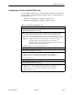
Table Of Contents
- Contents
- About This Guide
- About the FrameSaver DSL Unit
- User Interface and Basic Operation
- Configuration Procedures
- Configuration Options
- Overview
- Using the Easy Install Feature
- Setting Up So the Router Can Receive RIP
- Entering System Information and Setting the System Clock
- Configuration Option Tables
- Configuring the Overall System
- Configuring the Physical Interfaces
- Configuring Frame Relay for the Data Port
- Configuring ATM for the Network Interface
- Configuring Circuit and DLCI Records
- Configuring PVC Connections
- Setting Up Management and Communication Options
- Configuring Node IP Information
- Configuring Management PVCs
- Configuring General SNMP Management
- Configuring Telnet and/or FTP Session Support
- Configuring SNMP NMS Security
- Configuring SNMP Traps
- Configuring the Ethernet Port
- Configuring the Communication Port
- Configuring the COM Port to Support an External Modem
- Security and Logins
- Operation and Maintenance
- FTP Operation
- Troubleshooting
- Setting Up OpenLane for FrameSaver Devices
- Setting Up Network Health for FrameSaver Devices
- Menu Hierarchy
- SNMP MIBs and Traps, and RMON Alarm Defaults
- Connectors, Cables, and Pin Assignments
- Technical Specifications
- Equipment List
- Index

Configuration Options
4-15
9783-A2-GB20-00
July 2000
Table 4-6. Data Port Physical Interface Options (2 of 2)
Monitor DTR
Possible Settings: Enable, Disable
Default Setting: Enable
Specifies whether the state of the DTE Ready (DTR) circuit on the user data port will be
used to determine when valid data communication is possible with the DTE. When the
DTR off condition is detected, an alarm is generated, LMI is declared down, and no
further transfer of frame relay data can occur on this interface.
Enable – Interchange circuit CD (ITU 108/1/2) – DTR is monitored to determine when
valid data is sent from the DTE.
Disable – DTR is not monitored. DTR is assumed to be asserted and data is being
transmitted, regardless of the state of the lead.
Port (DTE) Initiated Loopbacks
Possible Settings: Local, Disable
Default Setting: Disable
Allows a local external DTE Loopback to be started or stopped via the port’s attached
data terminal equipment using the port’s interchange lead LL (ITU 141).
Local – The DTE attached to the port controls the local external DTE Loopback.
Disable – The DTE attached to the port cannot control the local external DTE
Loopback.