
User's Manual

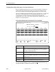

Table Of Contents
- Contents
- About This Guide
- 1. About the FrameSaver SLV
- 2. User Interface and Basic Operation
- 3. Configuration Procedures
- 4. Configuration Options
- Using the Easy Install Feature
- Using RIP with FrameSaver SLV CSU/DSUs
- Entering System Information and Setting the System Clock
- Setting Up the Modem
- Setting Up Auto-Configuration
- Setting Up Dial Backup
- PVC Backup Over the Network Interface
- Setting Up Back-to-Back Operation
- Configuration Option Tables
- Configuring the Overall System
- Configuring Physical Interfaces
- Assigning Time Slots/Cross Connections
- Configuring Frame Relay for an Interface
- Manually Configuring DLCI Records
- Configuring PVC Connections
- Configuring the IP Path List
- Setting Up Management and Communication Options
- Configuring the Criteria for Automatic Backup
- 5. Configuring the FrameSaver SLV Router
- FrameSaver SLV Router Overview
- IP Routing
- Address Resolution Protocol
- Proxy ARP
- Interface Configuration
- Network Address Translation
- Network Address Port Translation
- Dynamic Host Configuration Protocol Server
- DHCP Relay Agent
- Router Security
- Provisioning the Router Interface
- Configuring the Router Using Terminal Emulation
- 6. Security and Logins
- 7. Operation and Maintenance
- 8. Troubleshooting
- 9. Setting Up OpenLane for FrameSaver Devices and Activating SLM Features
- 10. Setting Up NetScout Manager Plus for FrameSaver Devices
- 11. Setting Up Network Health for FrameSaver Devices
- A. Menu Hierarchy
- B. SNMP MIBs and Traps, and RMON Alarm Defaults
- C. Router CLI Commands, Codes, and Designations
- D. Router Command Line Summaries and Shortcuts
- E. Connectors, Cables, and Pin Assignments
- F. Technical Specifications
- G. Equipment List
- Index

4. Configuration Options
4-56
September 2002 9128-A2-GB20-80
Only those DSX-1-to-Network assignments from page 1 are displayed on this
page, from left to right and top to bottom in ascending order, by network and time
slot.
When a CGA condition (LOS, OOF, or AIS) is declared for a T1 interface, the
signaling bits being transmitted to the other T1 interface for the DS0 are forced to
idle for two seconds (except for user-defined patterns which are transmitted
immediately). This drops any call in progress. The signaling bits are then forced to
the selected state (Busy or Idle), and remain in this state until the CGA condition
clears. At this point, the received signaling bits from the T1 interface which
formerly had the CGA condition are passed through to the other T1 interface.
NOTE:
Trunk conditioning will only occur on DS0s that are cross-connected to
another T1 interface. All other DS0s remain unaffected by trunk conditioning.
Enter one of the values shown in Table 4-12, Signaling and Trunk Conditioning
Values, in each of the fields on both the Network side and the DSX-1 side.
Although you can choose any value for the DSX-1 side, the default value displayed
is based on a typical setting that would be used with the corresponding Network
side value. Typical pairs of values are shown in the table below. If you change the
Network side value, the DSX side value is changed to the corresponding default
value.
Table 4-12. Signaling and Trunk Conditioning Values (1 of 3)
Network Side Meanings DSX-1 Side
None No signaling used on this DS0. Use this setting if
there is no voice signaling information being passed
on this DS0 (clear channel).
None
RBS (default) Robbed Bit Signaling is used on this DS0, but no
trunk conditioning. Signaling bits will be passed to the
T1 interface to which this DS0 is cross-connected
when this T1 interface is not in CGA, but the signaling
bits will be all ones when CGA is present.
RBS
The following values configure the cross-connect for RBS, as well as perform the
trunk conditioning. Although ABCD signaling bits for each setting are described,
only AB bits are transmitted when the cross-connected T1 network interface is
using D4 framing.