
User's Manual
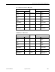
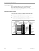
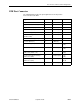
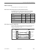
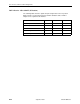
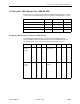
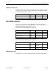

Table Of Contents
- Contents
- About This Guide
- 1. About the FrameSaver SLV
- 2. User Interface and Basic Operation
- 3. Configuration Procedures
- 4. Configuration Options
- Using the Easy Install Feature
- Using RIP with FrameSaver SLV CSU/DSUs
- Entering System Information and Setting the System Clock
- Setting Up the Modem
- Setting Up Auto-Configuration
- Setting Up Dial Backup
- PVC Backup Over the Network Interface
- Setting Up Back-to-Back Operation
- Configuration Option Tables
- Configuring the Overall System
- Configuring Physical Interfaces
- Assigning Time Slots/Cross Connections
- Configuring Frame Relay for an Interface
- Manually Configuring DLCI Records
- Configuring PVC Connections
- Configuring the IP Path List
- Setting Up Management and Communication Options
- Configuring the Criteria for Automatic Backup
- 5. Configuring the FrameSaver SLV Router
- FrameSaver SLV Router Overview
- IP Routing
- Address Resolution Protocol
- Proxy ARP
- Interface Configuration
- Network Address Translation
- Network Address Port Translation
- Dynamic Host Configuration Protocol Server
- DHCP Relay Agent
- Router Security
- Provisioning the Router Interface
- Configuring the Router Using Terminal Emulation
- 6. Security and Logins
- 7. Operation and Maintenance
- 8. Troubleshooting
- 9. Setting Up OpenLane for FrameSaver Devices and Activating SLM Features
- 10. Setting Up NetScout Manager Plus for FrameSaver Devices
- 11. Setting Up Network Health for FrameSaver Devices
- A. Menu Hierarchy
- B. SNMP MIBs and Traps, and RMON Alarm Defaults
- C. Router CLI Commands, Codes, and Designations
- D. Router Command Line Summaries and Shortcuts
- E. Connectors, Cables, and Pin Assignments
- F. Technical Specifications
- G. Equipment List
- Index

E. Connectors, Cables, and Pin Assignments
9128-A2-GB20-80 September 2002
E-15
T1 Network Cable (Feature No. 3100-F1-500)
Network access is via a 20-foot cable with an RJ48C unkeyed plug-type connector
on each end. The following table shows pin assignments and the purpose of each.
T1 Mass Termination Cable (Feature No. 9007-F1-500)
The following pin assignments are for the T1 Mass Termination cable that
connects multiple carrier-mounted FrameSaver units to an M66 block. It has a
50-pin RJ48H plug at one end and seven RJ48C plugs at the other end.
Function Circuit Direction Pin Number
Receive Ring R1 From Network 1
Receive Tip T1 From Network 2
Transmit Ring R To Network 4
Transmit Tip T To Network 5
Function Circuit Line # Pin # Function Circuit Line # Pin #
Receive ring
from the
network
R1 1
2
3
4
5
6
7
1
2
3
4
5
6
7
Transmit ring to
the network
R1
2
3
4
5
6
7
14
15
16
17
18
19
20
Receive tip
from the
network
T1 1
2
3
4
5
6
7
26
27
28
29
30
31
32
Transmit tip to the
network
T1
2
3
4
5
6
7
39
40
41
42
43
44
45