
User's Manual
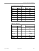
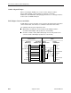
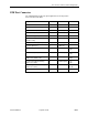
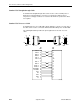
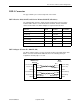
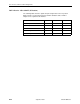
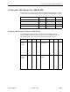
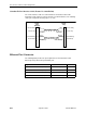
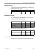

Table Of Contents
- Contents
- About This Guide
- 1. About the FrameSaver SLV
- 2. User Interface and Basic Operation
- 3. Configuration Procedures
- 4. Configuration Options
- Using the Easy Install Feature
- Using RIP with FrameSaver SLV CSU/DSUs
- Entering System Information and Setting the System Clock
- Setting Up the Modem
- Setting Up Auto-Configuration
- Setting Up Dial Backup
- PVC Backup Over the Network Interface
- Setting Up Back-to-Back Operation
- Configuration Option Tables
- Configuring the Overall System
- Configuring Physical Interfaces
- Assigning Time Slots/Cross Connections
- Configuring Frame Relay for an Interface
- Manually Configuring DLCI Records
- Configuring PVC Connections
- Configuring the IP Path List
- Setting Up Management and Communication Options
- Configuring the Criteria for Automatic Backup
- 5. Configuring the FrameSaver SLV Router
- FrameSaver SLV Router Overview
- IP Routing
- Address Resolution Protocol
- Proxy ARP
- Interface Configuration
- Network Address Translation
- Network Address Port Translation
- Dynamic Host Configuration Protocol Server
- DHCP Relay Agent
- Router Security
- Provisioning the Router Interface
- Configuring the Router Using Terminal Emulation
- 6. Security and Logins
- 7. Operation and Maintenance
- 8. Troubleshooting
- 9. Setting Up OpenLane for FrameSaver Devices and Activating SLM Features
- 10. Setting Up NetScout Manager Plus for FrameSaver Devices
- 11. Setting Up Network Health for FrameSaver Devices
- A. Menu Hierarchy
- B. SNMP MIBs and Traps, and RMON Alarm Defaults
- C. Router CLI Commands, Codes, and Designations
- D. Router Command Line Summaries and Shortcuts
- E. Connectors, Cables, and Pin Assignments
- F. Technical Specifications
- G. Equipment List
- Index

E. Connectors, Cables, and Pin Assignments
9128-A2-GB20-80 September 2002
E-17
Modem Connector
The dial modem interface/connector that is integrated into the FrameSaver unit is
an RJ11 6-position, 4-contact unkeyed modular jack. The following table shows pin
assignments and the purpose of each.
ISDN DBM Connector
The backup connection is through the DBM interface/connector, which is an
8-position keyed modular jack. The following tables show pin assignments for the
ISDN PRI and BRI DBMs and the purpose of each.
FrameSaver SLV 9128-II ISDN PRI pin assignments:
FrameSaver SLV 9126 ISDN BRI/U pin assignments:
ISDN Modular Cable
The ISDN cable comes with the FrameSaver unit ordered with the DBM feature.
Function Circuit Direction Pin Number
Ring R To Local Loop 2
Tip T To Local Loop 3
Function Circuit Direction Pin Number
PRI Receive Ring DBM1 From Local Loop 1
PRI Receive Tip DBM2 From Local Loop 2
PRI Transmit Ring DBM4 To Local Loop 4
PRI Transmit Tip DBM5 To Local Loop 5
Function Circuit Direction Pin Number
BRI Transmit/Receive Ring DBM4 To/From
Local Loop
4
BRI Transmit/Receive Tip DBM5 To/From
Local Loop
5