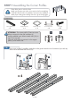
5 Gazebo GZ3DXL Aluminium Composite Roof Panels Assembly Instructions 9’7’’ 11 ’2 10 ’’ ’’ 7’ 15’9 ’6 ’’ ’’ 15’1 Paragon Group USA Customer Service:(877) 782 4482 Email:cs-outdoors@paragongroupusa.
Introduction Thank you for purchasing the Gazebo GZ3DXL. When properly assembled and maintained, this gazebo will provide many years of enjoyment! These instructions include helpful hints and important information needed to safely assemble and properly maintain the gazebo. Please read these instructions completely before you begin. Our patented gazebo has been designed for easy assembly. All steps can be completed by a team of four people. The assembly should take about two hours.
Safety Advice • The gazebo must be positioned and fixed on a flat level surface. • Dispose of all plastic bags safely. Keep them out of the reach of children. • Keep children and pets away from the assembly area until the work is completed. • Always wear shoes, gloves and safety goggles when working. • Take special care not to touch overhead power lines with the aluminium profiles. • Do not attempt to assemble the gazebo in windy or wet conditions.
List of Parts six contact customer service before beginning assembly: Customer Service:(877) 782 4482 Email:cs-outdoors@paragongroupusa.com No. 1 Profile Corner Profile 2190mm Qty Step 4 No.
No. Profile black side 19 Qty Step 4 7 Aluminium Composite Roof Panel No.
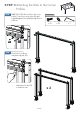
STEP 1 Assembling the Corner Profiles Place all the parts on a level surface. Make sure the pieces are in the correct positions before assembling. Carefully follow the order of assembly to ensure an easy installation. Wear proper safety gear including work shoes, gloves and goggles. Components Corner profile (1) Support frame (2) x4 Support plate (3) x4 x4 Roof connector (4) x4 1.
ATTENTION: Note: Do not need to assemble support frame (2) if you purchased the screen netting (GZ3DS or GZ3DXLS). 1.B 2 Slide support frames (2) over lower end of corner profiles (1). Attach support plates (3) to corner profiles as shown, using screws (33) for each plate.
STEP 2 Assembling the Rails NOTE: The Rails (5) have a preassembled connecting parts to be inserted into Rails (6). Components Rail (5) x2 x2 2.A x 16 x 14 x2 Rail (7) Screw (31) Inner Roof Connector (9) Rail (6) Rail (8) Outer Roof Connector (10) x2 x 18 Insert connecting part of rail (5) into blunt end of rail (6) as shown. Attach with four screws (31). Repeat to create four sets of rails. 31 2.B Insert connecting part of rail(7) into blunt end of rail(8) as shown.
2.C Attach four outer roof connectors (10) and three inner roof connectors(9) to each rail set at pre-drilled screw holes, using screws (32). 10 9 VIEW FROM SIDE 32 32 10 10 9 10 9 10 9 VIEW FROM THE TOP Attach five outer roof connectors (10) and four inner roof connectors(9) to each rail set at pre-drilled screw holes, using screws (32). 10 10 10 9 9 VIEW FROM SIDE 10 9 10 9 10 9 ATTENTION: Attach roof connectors facing exactly in the directions shown.
STEP 3 Attaching the Rails to the Corner Profiles 3.A Attach one roof profile set (5+6) to two corner profiles (1) as shown, using screws (32) and supplied magnetic hex key (45) through holes in profile set. Components Screw (32) x 32 5 32 39 3.B 1 Close holes in profile set with plastic caps #3 (39). 5 39 1 Repeat step 3.A and 3.B to create two sets.
3.C Using at least 3 people, attach the remaining two roof profile sets (5+8,6+7) to corner profiles (1), connecting all four corner profiles (1). Fasten with four screws (32) and supplied magnetic hex key (45) on each side. Close holes in profile sets with plastic caps #3 (39). 8,7 6,5 32 39 1 5 8 1 6 7 7 6 1 5 8 1 1 IMPORTANT: After this step you should place the gazebo frame in its desired location. Make sure all corners are squared at 90 degrees.
STEP 4 Securing the Gazebo to the Ground 4.A Fasten the gazebo frame to the ground, using four spikes (42) for each support plate. Lower support frames (2) to cover support plates (3). Components 1 2 1 Ground spike (42) x 16 42 3 3 Optional Securing the Gazebo to a Concrete Floor or Wood Deck Concrete Floor: Components 1. Using a concrete drill, drill holes into the concrete floor, corresponding to the holes in support plates (3). 2.
STEP 5 Installing the Lower Roof Gable Profiles ATTENTION: DO NOT ATTEMPT TO ASSEMBLE THIS ALONE ! Components Roof gable profile(11) Roof gable profile(12) 2469mm 1808mm x4 x2 U-shaped Connector(23) Roof Top Connector Beam(30) x4 Roof gable profile(13) 949mm x4 Screw (34) T - connector A (46) Roof gable profile(15) 1790mm x4 3. 11 Roof Profiles, roof panel sand gables must be aligned properly during assembly to minimize any possibility of leaking. 3. 14 2. 12 3. 13 x8 2. 2.
36 32 38 38 9 11 30 36 11 30 11 11 30 11 32 Install roof gable profiles (15). Using screws (50) nuts (38) connect top center connector (48) to top connector beam(30). Using screws (32)connect profiles (15) to inner roof connector (9) on long roof profiles sets (7,8) and the other end to roof top center connector(48).
29 30 30 31 29 36 31 31 31 29 29 30 29 36 36 30 36 Attach T-connectors (46) to underside of roof gable profiles (12,15) , using screws (32) as shown. Attach X-connectors (47) to underside of roof gable profiles (11) , using screws (32) as shown. Connect profile (13,14) to X-connector (47) and the other end to T-connector(9) using screws(32).
STEP 6 Installing the Horizontal Roof Profiles Components Screw(32) x 24 Roof profile(24) 1009mm Roof profile(25) 1000mm x2 Roof profile(26) 1000mm x2 x2 Roof profile(27) 823mm x2 Roof profile(28) 823mm Corner cap(49) x 4 x2 Screw(33) x8 6.A Attach roof gable profiles (24,25,26,27,28) toT-connectors A (46) and X-connectors B (47).
STEP 7 Installing the Roof Panels and Upper Roof Profiles IMPORTANT: Gently cut on the edge of the panels on both side with knife and remove protective plastic of roof panels. Place with black surface toward the sun facing out when installing.
15 37 to 16 16 15 15 15 15 16 37 18 of 24
Components Roof profile(11A) 2220mm x4 Roof profile(12A) 1623mm x2 Roof profile(13A) 942mm x4 Roof profile(14A) 942mm x4 Roof profile(15A) 1623mm Screw(35) x 56 x4 Place roof profile (15A) on top of roof profile (15) as shown and fasten with screws (35) from below (inside gazebo). 15A 15 15A 16 24 25 17 15 15 16 17 35 ATTENTION: Roof Profiles, roof panels and gables must be aligned properly during assembly to minimize any possibility of leaking.
14,15 18 and fasten with screws(37) to outer roof connector(10) from below. 14 18 15 18 15 14 37 15A 15 , and fasten with two screws(35) from below(inside gazebo).
Fit roof panel(19,20,21,22) on top of roof profiles(11,12,13,14) as shown and fasten with one screw (37) to outer roof connector(10). Place roof profiles(11A) on top on roof profiles(11) and fasten with screws(35) from below.
Continue in a clock-wise direction as shown. 11A 13A 19 15A 17 15A 14A 18 16 11A 20 19 20 14A 13A 21 22 12A 12A 21 22 13A 19 18 20 11A 14A 17 16 15A 15A Place the roof panel (19,20) on top of profiles (11,13,14) , fasten with screw (37) from below. Place the roof gable profile (11A) on top of (11) , fasten with screw(35) from below of (11).
7.J Place the roof gable profile(13A) on top of(13), fasten with screw(35) from below of (13). 13A 13 STEP 8 Installing the Plastic Caps Components 12/13/14/15 11 41 40 Plastic Cap #1 (40) x 14 Plastic Cap #2 (41) x4 Close off roof profiles (12/13/14/15) with plastic caps #1(40) and roof profiles (11) with plastic caps #2 (41).
Gazebo GZ3DXL Aluminium Composite Roof Panels Assembly Instructions WARRANTY: Warranty covers damage due to manufacturing defects only. Warranty does not cover weather inflicted damage (Force Majeure) and/or damages caused by not following assembly instructions and adhering to warnings in manual. ATTENTION: Roof profiles,roof panels and gables must be aligned properly during assembly to minimize any possibility of leaking.