Introduction Thank you for purchasing the 12’ x 20' Louver Pergola . When properly assembled and maintained, this gazebo will provide many years of enjoyment! These instructions include helpful hints and important information needed to safely assemble and properly maintain the gazebo. Please read these instructions completely before you begin. Our patented gazebo has been designed for easy assembly. All steps can be completed by a fem of four people. The assembly should take about two hours.
“Safety Advice ¢ The gazebo must be positioned and fixed on a flat level surface. * Dispose of all plastic bags safely. Keep them out of the reach of children. ® Keep children and pets away from the assembly area until the work is completed. e Always wear shoes, gloves and safety goggles when working. * Take special care not fo touch overhead power lines with the aluminum profiles. * Do not attempt fo assemble the gazebo in windy or wet conditions.
List of Parts a The pergola is shipped in sight cartons, These cartons are heavy. Be careful when lifting them. Wear proper safety gear incl using work shoes, gloves and goggles. The parts are identified by removable stickers. Place all the parts for each step in staging areas, checking that you have all parts as you go. If any pairs are missing or damaged, contact customer service before beginning assembly: \_ Customer 782 4482 No.
No, Park Qly | Step | No.
Ne, Part Step | | No, Part Qly | Step Roof Profile connector Puller connector Roof Profile connector Comer profile cover 207 b> << Roof Profile connector Controller cover 35A Sx 3||45 Ra of Profile connector Controller Roof Profile connector Ring cap 36A 636 1367 Screw Roof Profile connector M4x10mm 1367 Roof Profile connector 20m 268 [23,45 Screw Stopper 174% 5mm 156] 6 Louver puller 312| 4 Screw Louver puller Louver puller 370mm 8 of 32
No, Park Qly | Step | No. Part Qty | Step <> 53 SD 328 3467] Nut 1/4" Sacker 54 31867 1/4" ‘Washer 57 2 236 gu 43 raw Pin Sei We included extra screws for your convenience.
STEP 1 Assembling the Louvers Place all the parts on a level surface. Make sure the pieces are in the comet positions before assembling. Carefully follow the order of assembly fo ensure an easy installation. Wear proper safely gear including work shoes, gloves and goggles. Components Attach louver connector (15) on louver (10) by screw (47). _— Louver{10} Louver connector) Screw(47) x 156 x 312 x 624 x 156 IMPORTANT: Make sure all the louver connectors installed in correct direction as shown.
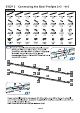
STEP 2 Connecting the Roof Profiles 6+7 ~ 8+8 Components ia ve Ce Roof Profile(s) Roof Profile(7) Roof Profile(8) Roof Profile(9) Comer profile cover{16) Comer profile cover{17) SIE ewe Connect roof profile (6,7) and (8,9) by roof profile connector (21,20) with screw (48) on the TOP and screw (49) on the SIDE and BOTTOM as shown. Insert roof profile connector (18,19) into roof profile (6/9) and fasten with two screw (49) each as shown.
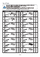
STEP 3 Connecting the Roof Profiles 2+3 ~ 4+5 Components = EEE ET Roof Profile(2) Roof Profitless) Roof Profile(3) Roof Profitless) Roof Profiterole) Roof Profile Roof Profile Roof Profile Roof Profile Roof Profile connector{20) connector) connector} connector{24) Roof Profile Roof Profile Roof Profile Roof Profile Roof Profile connector) connector) connectable) connector} Comptroller) Ring caplet} Scrawl) Scarecrow) Sawdust) x2 x2 x4 x12 x 102 Roof Profiteer) x2 Sy Roo Profile connector) x2 Roof Profile co
Insert roof profile connector (24/25) into hollow ends of roof profile (5,4) with two prevailed holes facing | inside as shown, and fasten with screw (49). Insert roof profile connector (26/27) into hollow end. of roof profile (5,4) with two prevailed holes facing upward at the same position of roof profile (5,4) per-drilled holes as shown for later step. Attach corner profile cover {43) on connector roof profile 4A+5A by 2 screw {49) from underneath.
Insert roof profile connector (36A/35A) into hollow ends of roof profile (2A,3A) and fasten with two screw (49) on the side as shown. Insert roof profile connector (34) into hollow ends of roof profile (2A,3A) and fasten with ONE screw (49) at the furthest position of the three per-drilled holes as shown. Insert controller (45) info roof profile (2), fasten with screw (61) and nut (53) fo the side of control ler {45) as shown.
iil Place roof profile set (5+5A+4A+4) as in U format as shown. Connect roof profile set to roof profile set by fasten screw (49) from underneath of corner profile cover (17,16) to roof profile {4+5) as shown. Connect roof profile set (2+3) on middle of roof profile set {5+5A+4A+4) by attaching roof profile connector (37) from & underneath of roof profile set by screw {49). {2+3) on smooth surface article fo have the same level with roof profile sel for easy installation.
Attach roof profile connector {14) to the end of roof profile fasten with screw (49). Insert roof profile connector (23,22) into roof profile attach roof profile connector (13} to the end of roof profile (7,4) and (9,5) by screw (49) as shown.
Attach screw (51) on louver mount {28,29,30,31) with nut (53) as shown. BH BH x2 Barr rrr rr BB x6 IMPORTANT: Screw 5 head must be vertically installed on louver mount (28,29,30,31). Insert louver mount (28,29) into roof profile with marked arrow point outward as shown. Insert louver mount (30,31) into roof profile with marked arrow point outward as shown.
Connect roof profile set (4+4A+5A+5) to roof profile frame by fasten screw (49) from underneath of corner profile cover (17,16) as shown. Connect roof profile set (2+3) on middle of roof profile set by attaching roof profile connector (37) from underneath of roof profile set by screw (49) as shown.
Attach roof profile connector (14) to the end of roof profile fasten with screw (49). Attach roof profile (2A+3A) on corner profile cover(43) by screw (49) from underneath. 28 in Insert roof profile connector (23,22) into roof profile attach roof profile connector “TE = (13) to the end of roof profile {7,4} and (9,5) by screw (49} as shown. < Insert roof profile connector (23,22) into roof profile attach roof profile connector (13) to the end of roof profile (7,4) and (9,5) by screw (49) as shown.
STEP § Building the Corner Profiles Components Align per-drilled screw holes in comer with screw holes in support — plate(8). Attach support plate(11) to corner profiles(1) as Comer Profile(1) Comer Profitable) shown, using two screws(49) for each plate. x4 x2 Support Plate(11) Support Plate(12} Scrawl} Using at least 3 people, lift roof frame. Align per-drilled screw holes on the top of corner .
STEP ¢ Installing the Louvers 6A [Referrer | Place 5 piece louvers (10) lino per-installed screw (51) beside roof profile (5), fasten with nut (54) on both side of louver (10) as Louver puller{39} Louver puller(40} Louver puller{41) shown. Screw(48) Screw(50) Nuisance) Nu) Ennui) x4 x 156 x 4 x312 x 156 IMPORTANT: Make sure All Louvers(10) installed at the same direction as shown. >’ Insert one side of the louvers(10} ~ into screwball) with a slop, than x3 9 place another end.
Connect louver by screw(48) and shown. connectors(15), fasten with screw(50) as shown. with louver puller pieces louvers(10) at a time. Repeat to finish left side Louvers. Place plastic washer(56) between louver puller and louver Repeat to assemble louvers{10) on the roof profile frame and connect ATTENTION: Screw(50) must fastened toward Kiddie roof IMPORTANT: Louver puller(40) hanger must installed ot the same side of louver connectable.
Place 5 piece louvers (10) info per-installed screw (51) beside roof profile (4), fasten with nut (54) on both of louver (10) as shown. IMPORTANT: Make sure AlL Louvers(10) installed al the same direction as shown. inset! one side of the louvers{10} into screw{5 1} with a slop, than place another end. ATTENTION: DO NOT OVER TIGHTEN SCREW(54).
Connect louver by screw{48) and shown. Place plastic washer(56) between louver puller and louver connectable, fasten with screw(50) as shown. Repeat to assemble louvers(10) on the roof profile frame and connect with louver puller pieces louvers(10) at a time. Repeat to finish left side Louvers. IMPORTANT: ATTENTION: Louver puller(40) hanger must Screw(50) must fastened installed at the same side of toward Kiddie roof louver connectors(15).
Place 5 piece louvers (10) into per-installed screw : (51) beside roof profile (5), fasten with nut (54) on both side of louver (10) as shown. =. IMPORTANT: {. Make sure All Louvers(10] installed al the same direction as shown. inset! one side of the louvers{10} into screw{5 1} with a slop, than place another end.
6.F Connect louver by screw(48) and shown. Place plastic washer(56) between louver puller and louver connectors(15), fasten with screw{50) as shown. Repeat to assemble louvers{10) on the roof profile frame and connect with louver puller pieces louvers(10) at a time. Repeat to finish left side Louvers. A ATTENTION: Screw{50) must fastened toward Kiddie roof important: {> Louver puller(40) hanger must installed at the same side of louver connectors(15).
Place 5 piece louvers (10) into per-installed screw (51) beside roof profile with nut (54) on both of louver (10) as shown. #L IMPORTANT: {. Make sure All Louvers(10] installed al the same direction as shown. inset! one side of the louvers{10} into screw{5 1} with a slop, than place another end. A ATTENTION: £. DO NOT OVER TIGHTEN SCREW(54).
Connect louver by screw{48) and shown. Place plastic washer(56) between louver puller and louver connectable, fasten with screw(50) as shown. Repeat to assemble louvers(10) on the roof profile frame and connect with louver puller pieces louvers(10) at a time. Repeat to finish left side Louvers. IMPORTANT: ATTENTION: Louver puller(40) hanger must Screw(0) must fastened installed a the same side of toward Kiddie roof louver connectors(15).
STEP 2& Securing the Gazebo to a Concrete Floor or Wood Deck Concrete Floor: 1. Using a concrete drill, drill holes into the concrete floor, OE=mm 00 corresponding to the holes in support plates {8}. Concrete Boise, washers 2. Insert concrete bolts into the holes and hammer into place, using a mallet. 59 3. Fasten concrete bolts with washers and nuts. x24 o « Wood Deck: 1. Using an electric wood drill, drill holes info the wood floor, Pst corresponding to the holes in support plates [8].
Center of Post/Footing Measurements 97.8 2943 4mm 2942 Arm 1910.07 £044 Bros lore] 2942. 4mm NAY (97. NS [7.
ASST piss 12’ x 20’ Louver Pergola Assembly Instructions WARRANTY: Warranty covers damage due fo manufacturing defects only for a period of 5 years on the structure from date of purchase. Warranty does not cover weather inflicted damage and/or damages causes caused by not following assembly instructions and adhering to warnings in manual. Warranty does not cover user error, negligence, or misuse. /N\ WARNING: Cancer and Reproductive Harmwww.P65Warnings.ca.gov. {\ ADVERTISEMENT: Cancer et Troubles de |’ appa