
Datasheet
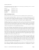


Parallax, Inc. • RFID Reader Module (#28140) •Updated 09/2005 v1.1 Page 3
Communication Protocol
Implementation and usage of the RFID Reader Module is straightforward. BASIC Stamp 1, 2, and
SX28AC/DP code examples (SX/B) are included at the end of this documentation.
The RFID Reader Module is controlled with a single TTL-level active-low /ENABLE pin. When the /ENABLE
pin is pulled LOW, the module will enter its active state and enable the antenna to interrogate for tags.
The current consumption of the module will increase dramatically when the module is active.
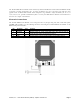
A visual indication of the state of the RFID Reader Module is given with the on-board LED. When the
module is successfully powered-up and is in an idle state, the LED will be GREEN. When the module is in
an active state and the antenna is transmitting, the LED will be RED.
The face of the RFID tag should be held parallel to the front or back face of the antenna (where the
majority of RF energy is focused). If the tag is held sideways (perpendicular to the antenna) you'll either
get no reading or a poor reading. Only one transponder tag should be held up to the antenna at any
time. The use of multiple tags at one time will cause tag collisions and confuse the reader. The two tags
available in the Parallax store have a read distance of approximately 3 inches. Actual distance may vary
slightly depending on the size of the transponder tag and environmental conditions of the application.
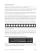
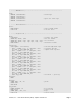
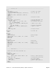
When a valid RFID transponder tag is placed within range of the activated reader, the unique ID will be
transmitted as a 12-byte ASCII string via the TTL-level SOUT (Serial Output) pin in the following format:
Unique ID
Digit 1
MSB LSB
Start Byte
(0x0A)
Unique ID
Digit 2
Unique ID
Digit 3
Unique ID
Digit 4
Unique ID
Digit 5
Unique ID
Digit 6
Unique ID
Digit 7
Unique ID
Digit 8
Unique ID
Digit 9
Unique ID
Digit 10
Stop Byte
(0x0D)
The start byte and stop byte are used to easily identify that a correct string has been received from the
reader (they correspond to a line feed and carriage return characters, respectively). The middle ten bytes
are the actual tag's unique ID.
All communication is 8 data bits, no parity, 1 stop bit, non-inverted, least significant bit first (8N1). The
baud rate is configured for 2400bps, a standard communications speed supported by most any
microprocessor or PC, and cannot be changed. The Parallax RFID Reader Module initiates all
communication. The Parallax RFID Reader Module can connect directly to any TTL-compatible UART or to
an RS232-compatible interface by using an external level shifter.
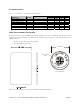
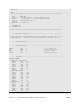
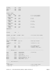
Absolute Maximum Ratings and Electrical Characteristics
Condition Value
Operating Temperature -40ºC to +85ºC
Storage Temperature -55ºC to +125ºC
Supply Voltage (V
CC
) +4.5V to +5.5V
Ground Voltage (V
SS
) 0V
Voltage on any pin with respect to V
SS
-0.3V to +7.0V
Stresses above those listed under “Absolute Maximum Ratings” may cause permanent damage to the
device. This is a stress rating only and functional operation of the device at those or any other conditions
above those indicated in the operation listings of this specification is not implied. Exposure to maximum
rating conditions for extended periods may affect device reliability.