
RFID reader documentation

Parallax, Inc. • RFID Reader Module (#28140) •Updated 09/2005 v1.1 Page 2
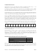
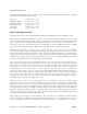
The Parallax RFID Reader Module works exclusively with the EM Microelectronics-Marin SA EM4100-family
of passive read-only transponder tags. A variety of different tag types and styles exist with the most
popular made available from Parallax. Each transponder tag contains a unique identifier (one of 2
40
, or
1,099,511,627,776, possible combinations) that is read by the RFID Reader Module and transmitted to
the host via a simple serial interface.
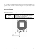
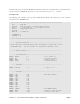
Electronic Connections
The Parallax RFID Reader Module can be integrated into any design using only four connections (VCC,
/ENABLE, SOUT, GND). Use the following circuit for connecting the Parallax RFID Reader Module to the
BASIC Stamp microcontroller:
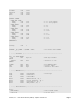
Pin Pin Name Type Function
1 VCC P System power, +5V DC input.
2 /ENABLE I Module enable pin. Active LOW digital input. Bring this pin LOW to
enable the RFID reader and activate the antenna.
3 SOUT O Serial Out. TTL-level interface, 2400bps, 8 data bits, no parity, 1 stop bit.
4 GND G System ground. Connect to power supply’s ground (GND) terminal.
Note: Type: I = Input, O = Output, P = Power, G = Ground