
Robotics with the Boe-Bot text v2.2

Chapter 3: Assemble and Test Your Boe-Bot · Page 101
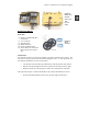
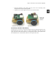
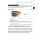
√ From the underside of the chassis, pull any excess servo and battery cable
through the hole with the rubber grommet.
√ Tuck the excess cable lengths between the servos and the chassis.
Figure 3-12
Assembled
Boe-Bots
With Board of Education Rev C With HomeWork Board
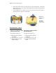
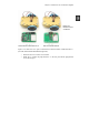
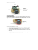
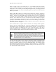
ACTIVITY #2: RE-TEST THE SERVOS
In this activity, you will test to make sure that the electrical connections between your
board and the servos are correct. Figure 3-13 shows your Boe-Bot’s front, back, left, and
right. We need to make sure that the servo on the right turns when it receives pulses from
P12 and that the servo on the left turns when it receives pulses from P13.