
Robotics with the Boe-Bot text v2.2


Appendix D: Breadboarding Rules · Page 315
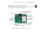
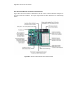
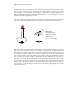
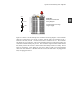
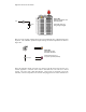
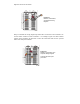
the prototyping area (Figure D-7). In the schematic, the other lead of the resistor is
connected to not one, but two other component terminals. A terminal from the
photoresistor and capacitor both share this connection. On the breadboard, the other
resistor lead is plugged into one of the rows of 5 sockets. This row also has leads from
the capacitor and photoresistor plugged into it. In the schematic, the other terminals of
the photoresistor and capacitor are connected to Vss. Here is a trick to keep in mind
when building circuits on a breadboard. You can use a wire to connect an entire row on
the breadboard to another row, or even to I/O pins or power terminals such as Vdd or
Vss. In this case, a wire was used to connect Vss to a row on the breadboard. Then, the
leads for the capacitor and photoresistor were plugged into the same row, completing the
circuit.
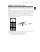
Vss
220
Ω
P6
0.1 µF
Figure D-6
Resistor, Photoresistor, and
Capacitor Schematic