
Ping mounting bracket documentation v2.0

Copyright © Parallax, Inc. • PING))) Bracket Kit (#570-28015) • v1.1 8/10/2007 Page 4 of 4
Breadboard Connection
A breadboard connection will be necessary if you are using a
custom board/robot or any of the following boards with your
Boe-Bot robot:
• Serial Board of Education Rev A
• Serial Board of Education Rev B
• BASIC Stamp HomeWork Board
It is also useful if you have a servo port jumper, but wish to
keep your servos connected to Vin.
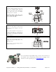
The PING))) sensor requires a 5 VDC power supply. To make the connections directly from the
breadboard:
1. Connect the servo extension cable to the PING))) sensor: Black to GND, Red to 5 V, and White to SIG.
2. Place a 3-pin male/male header in the other end of the cable, and plug it into the breadboard. Be sure to
position the cable where it won’t interfere with the sensor when the bracket rotates.
3. Using jumper wires, connect the Black lead to Vss, the Red lead to Vdd, and the White lead to I/O pin P15, as
shown.
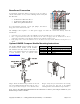
Optional HM55B Compass Module Mounting Instructions
The Parallax HM55B Compass Module may also
be mounted on the bracket, on the backside.
The hardware for this, shown in the table at
right, is not included but may be obtained from
a local hardware store or ordered from
www.parallax.com
.
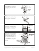
Step 1: Mount the HM55B Compass Module on the back
side of the PING))) Mounting Bracket using (2) 4/40 ½”
screws, (2) 4/40 nuts and (2) 10” servo extension cables.
Step 2: Verify that your work matches the drawing
avove, that shows the back side of the PING)))
Mounting Bracket with an HM55B Compass Module.
Note: refer to the HM55B documentation for the schematic to connect your Compass Module to your
BASIC Stamp or other controller.
Part# Qty Description
29123 1 HM55B Compass Module
805-00002 2 14” extension cable w/ 3-pin header
700-00016 2 4/40 1/2” screw
700-00003 2 4/40 nut