Propeller™ P8X32A Datasheet 8-Cog Multiprocessor Microcontroller 1.0 PRODUCT OVERVIEW 1.1. Introduction The Propeller chip is designed to provide high-speed processing for embedded systems while maintaining low current consumption and a small physical footprint.
Propeller™ P8X32A Datasheet www.parallax.com Table of Contents 1.0 Product Overview......................................................... 1 1.1. 1.2. 1.3. 1.4. 1.5. 1.6. 1.7. Introduction ................................................................................1 Stock Codes...............................................................................1 Key Features..............................................................................3 Programming Advantages............................
Propeller™ P8X32A Datasheet 1.3. www.parallax.com Key Features The design of the Propeller chip frees application developers from common complexities of embedded systems programming. For example: 1.6. Parallax Inc. supports the Propeller chip with a variety of hardware tools and boards: • Propeller Clip (#32200) and Propeller Plug (#32201). These boards provide convenient programming port connections, see the Typical Connection Diagrams on Page 5.
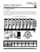
Propeller™ P8X32A Datasheet www.parallax.com 2.0 CONNECTION DIAGRAMS 2.1. Pin Assignments LQFP and QFN Packages DIP Package 2.2. Pin Descriptions Table 2: Pin Descriptions Pin Name Direction Description General purpose I/O Port A. Can source/sink 40 mA each at 3.3 VDC. CMOS level logic with threshold of ≈ ½ VDD or 1.6 VDC @ 3.3 VDC. The pins shown below have a special purpose upon power-up/reset but are general purpose I/O afterwards. P28 - I2C SCL connection to optional, external EEPROM.
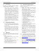
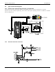
Propeller™ P8X32A Datasheet 2.3. www.parallax.com Typical Connection Diagrams 2.3.1. Propeller Clip or Propeller Plug Connection - Recommended Note that the connections to the external oscillator and EEPROM, which are enclosed in dashed lines, are optional. Propeller Clip, Stock #32200; Propeller Plug, Stock #32201. The Propeller Clip/Plug schematic is available for download from www.parallax.com. 2.3.2. Alternative Serial Port Connection Copyright © Parallax Inc. Page 5 of 37 Rev 1.
Propeller™ P8X32A Datasheet 3.0 OPERATING PROCEDURES 3.1. Boot-Up Procedure www.parallax.com Upon power-up, or reset: 1. The Propeller chip’s internal RC oscillator begins running at 20 kHz, then after a 50 ms reset delay, switches to 12 MHz. Then the first processor (Cog 0) loads and runs the built-in Boot Loader program. 2. The Boot Loader performs one or more of the following tasks, in order: a. Detects communication from a host, such as a PC, on pins P30 and P31.
Propeller™ P8X32A Datasheet 4.3. www.parallax.com Cogs (processors) The Propeller contains eight (8) identical, independent processors, called cogs, numbered 0 to 7. Each cog contains a Processor block, local 2 KB RAM configured as 512 longs (512 x 32 bits), two advanced counter modules with PLLs, a Video Generator, I/O Output Register, I/O Direction Register, and other registers not shown in the Block Diagram.
Propeller™ P8X32A Datasheet 4.5. www.parallax.com I/O Pins A. A pin is an input only if no active cog sets it to an output. B. A pin outputs low only if all active cogs that set it to output also set it to low. C. A pin outputs high if any active cog sets it to an output and also sets it high. Table 3 demonstrates a few possible combinations of the collective cogs’ influence on a particular I/O pin, P12 in this example.
Propeller™ P8X32A Datasheet 4.8. www.parallax.com Assembly Instruction Execution Stages Figure 4: Assembly Instruction Execution Stages Stage 1 2 3 4 5 (Execute N- 1) Fetch Instruction N Write Result N-1 Fetch Source N Fetch Destination N (Execute N) Fetch Instruction N+1 Write Result N M M+1 M+2 M+3 M+4 M+5 clock cycle The Propeller executes assembly instructions in five stages.
Propeller™ P8X32A Datasheet 4.9. www.parallax.com Cog Counters Each cog has two counter modules: CTRA and CTRB. Each counter module can control or monitor up to two I/O pins and perform conditional 32-bit accumulation of its FRQ register into its PHS register on every clock cycle. Each counter module also has its own phase-locked loop (PLL) which can be used to synthesize frequencies up to 128 MHz.
Propeller™ P8X32A Datasheet www.parallax.
Propeller™ P8X32A Datasheet www.parallax.com The 2-bit VMode (video mode) field selects the type and orientation of video output, if any, according to Table 8. The VPins (video output pins) field is a mask applied to the pins of VGroup that indicates which pins to output video signals on. Table 8: The Video Mode Field Table 11: The VPins Field VMode Video Mode 00 Disabled, no video generated.
Propeller™ P8X32A Datasheet www.parallax.com VGA mode, each 8-bit color value is written to the pins specified by the VGroup and VPins field. For VGA typically the 8 bits are grouped into 2 bits per primary color and Horizontal and Vertical Sync control lines, but this is up to the software and application of how these bits are used. For composite video each 8-bit color value is composed of 3 fields. Bits 0-2 are the luminance value of the generated signal.
Propeller™ P8X32A Datasheet 4.11. www.parallax.com Use Spin's CLKSET command when possible (see sections 6.3 and 6.4) since it automatically updates all the abovementioned locations with the proper information. CLK Register The CLK register is the System Clock configuration control; it determines the source and characteristics of the System Clock. It configures the RC Oscillator, Clock PLL, Crystal Oscillator, and Clock Selector circuits (See the Block Diagram, page 1).
Propeller™ P8X32A Datasheet www.parallax.com 5.0 MEMORY ORGANIZATION 5.1. Main Memory The Main Memory is a block of 64 K bytes (16 K longs) that is accessible by all cogs as a mutually-exclusive resource through the Hub. It consists of 32 KB of RAM and 32 KB of ROM. Main memory is byte, word and long addressable. 5.1.1. Main RAM The 32 KB of Main RAM is general purpose and is the destination of a Propeller Application either downloaded from a host or from the external 32 KB EEPROM. 5.1.2.
Propeller™ P8X32A Datasheet www.parallax.com Figure 8 Propeller Character Interleaving As shown in Figure 8, The character pairs are merged row-by-row such that each character's 16 horizontal pixels are spaced apart and interleaved with their neighbors' so that the even character takes bits 0, 2, 4, ...30, and the odd character takes bits 1, 3, 5, ...31. The leftmost pixels are in the lowest bits, while the rightmost pixels are in the highest bits.
Propeller™ P8X32A Datasheet 6.0 www.parallax.com PROGRAMMING LANGUAGES The Propeller chip is programmed using two languages designed specifically for it: 1) Spin, a high-level object-based language, and 2) Propeller Assembly, a low-level, highly-optimized assembly language. There are many hardware-based commands in Propeller Assembly that have direct equivalents in the Spin language.
Propeller™ P8X32A Datasheet 6.2. www.parallax.com Math and Logic Operators Table 17: Math and Logic Operators Operator Level 1 Highest (0) 1 2 3 4 5 6 7 8 2 Constant 3 Expressions Is Unary Description Normal Assign -- always 9 Pre-decrement (--X) or post-decrement (X--). ++ always 9 Pre-increment (++X) or post-increment (X++). ~ always 9 Sign-extend bit 7 (~X) or post-clear to 0 (X~). ~~ always 9 Sign-extend bit 15 (~~X) or post-set to -1 (X~~).
Propeller™ P8X32A Datasheet 6.3. www.parallax.com Spin Language Summary Table Returns Value Spin Command ABORT 〈Value〉 9 Description Exit from PUB/PRI method using abort status with optional return value. BYTE Symbol 〈[Count]〉 Declare byte-sized symbol in VAR block. 〈Symbol〉 BYTE Declare byte-aligned and/or byte-sized data in DAT block. Data 〈[Count]〉 BYTE [BaseAddress] 〈[Offset]〉 9 Read/write byte of main memory. Symbol.
Propeller™ P8X32A Datasheet www.parallax.com Returns Value Spin Command ((IF ┆ IFNOT)) Condition(s) IfStatement(s) 〈ELSEIF Condition(s) ElseIfStatement(s)〉… 〈ELSEIFNOT Condition(s) ElseIfStatement(s)〉… 〈ELSE ElseStatement(s)〉 Description Test condition(s) and execute block of code if valid. IF and ELSEIF each test for TRUE. IFNOT and ELSEIFNOT each test for FALSE. INA 〈[Pin(s)]〉 9 Input register for 32-bit ports A. LOCKCLR (ID) 9 Clear semaphore to false and get its previous state; TRUE or FALSE.
Propeller™ P8X32A Datasheet www.parallax.com Returns Value Spin Command Description STRSIZE (StringAddress) 9 Get size, in bytes, of zero-terminate string. TRUNC (FloatConstant) 9 Remove fractional portion from floating-point constant at compile-time, in any block. VAR Size Symbol 〈[Count]〉 〈((,┆ Declare symbolic global variables. Size )) Symbol 〈[Count]〉〉… VCFG 9 Video Configuration register. VSCL 9 Video Scale register. WAITCNT (Value) Pause cog’s execution temporarily.
Propeller™ P8X32A Datasheet 6.4. www.parallax.com Propeller Assembly Instruction Table The Propeller Assembly Instruction Table lists the instruction’s 32-bit opcode, outputs and number of clock cycles. The opcode consists of the instruction bits (iiiiii), the “effect” status for the Z flag, C flag, result and indirect/immediate status (zcri), the conditional execution bits (cccc), and the destination and source bits (ddddddddd and sssssssss).
Propeller™ P8X32A Datasheet iiiiii zcri cccc ddddddddd sssssssss 010111 0011 1111 ????????? sssssssss www.parallax.
Propeller™ P8X32A Datasheet 6.4.1. www.parallax.com Assembly Conditions Condition Instruction Executes IF_ALWAYS always IF_NEVER never IF_E if equal (Z) 6.4.4. Assembly Operators Propeller Assembly code can contain expressions, which may use any operators allowed in constant expressions. The table (a Table 17) lists the operators allowed in Assembly.
Propeller™ P8X32A Datasheet 7.0 www.parallax.com PROPELLER DEMO BOARD SCHEMATIC The Propeller Demo Board (Stock #32100) provides convenient connections to 32K EEPROM, replaceable 5 MHz crystal, 3.
Propeller™ P8X32A Datasheet www.parallax.com 8.0 ELECTRICAL CHARACTERISTICS 8.1. Absolute Maximum Ratings Stresses in excess of the absolute maximum ratings can cause permanent damage to the device. These are absolute stress ratings only. Functional operation of the device is not implied at these or any other conditions in excess of those given in the remainder of Section 7.0. Exposure to absolute maximum ratings for extended periods can adversely affect device reliability.
Propeller™ P8X32A Datasheet www.parallax.com 9.0 CURRENT CONSUMPTION CHARACTERISTICS 9.1. Typical Current Consumption of 8 Cogs This figure shows the typical current consumption of the Propeller under various operating conditions duplicated across all cogs. Brown out circuitry and the Phase-Locked Loop were disabled for the duration of the test. Current consumption is substantially constant over the operational temperature range.
Propeller™ P8X32A Datasheet 9.2. www.parallax.com Typical Current of a Cog vs. Operating Frequency This graph shows a cog’s typical current consumption under various conditions, in isolation of other sources of current within the Propeller chip. Typical Current of a Cog vs. Operating Frequency (Vdd = 3.3 V, Ta = 25° C) 14 Spin Loop (REPEAT) Assembly Loop (JMP) 12 WAIT(CNT/PEQ/PNE) Current (mA) 10 8 6 4 2 0 0 10 20 30 40 50 60 70 80 90 100 Frequency (MHz) 9.3.
Propeller™ P8X32A Datasheet 9.4. www.parallax.com Typical Crystal Drive Current This graph shows the current consumption of the crystal driver over a range of crystal frequencies and crystal settings, all data points above 25 MHz were obtained by using a resonator since the driver does not perform 3rd harmonic overtone driving required for crystals over 25 MHz. Typical Crystal Drive Current (Vdd = 3.3 V, Ta = 25° C) 1.4 xtal1 xtal2 1.2 xtal3 Current (mA) 1.0 0.8 0.6 0.4 0.
Propeller™ P8X32A Datasheet 9.6. www.parallax.com Current Profile at Various Startup Conditions The diagrams below show the current profile for various startup conditions of the Propeller chip dependent upon the presence of an EEPROM and PC. Figure 9 Boot Sequence Current Profile for no PC and no EEPROM (P31 held low and P29 not connected (same as held low)). Figure 10 Boot Sequence Current Profile for PC (connected but idle) and no EEPROM. (P31 held high and P29 not connected).
Propeller™ P8X32A Datasheet www.parallax.com 10.0 TEMPERATURE CHARACTERISTICS 10.1. Internal Oscillator Frequency as a Function of Temperature While the internal oscillator frequency is variable due to process variation, the rate of change as a function of temperature when normalized provides a chip invariant ratio which can be used to calculate the oscillation frequency when the ambient temperature is other than 25 °C (the temperature to which the graph was normalized).
Propeller™ P8X32A Datasheet 10.2. www.parallax.com Fastest Operating Frequency as a Function of Temperature The following graph represents a small sample average of a Propeller chip’s fastest operating range. The test was performed in a forced air chamber using code run on all eight cogs, multiple video generators, and counter modules. A frequency was considered successful if the demo ran without fault for one minute.
Propeller™ P8X32A Datasheet 10.3. www.parallax.com Current Consumption as a Function of Temperature The following graph demonstrates the current consumption of the Propeller as a function of temperature. It is clear from the graph that current consumption is nearly independent of temperature over the entire military temperature range.
Propeller™ P8X32A Datasheet www.parallax.com 11.0 PACKAGE DIMENSIONS 11.1. P8X32A-D40 (40-pin DIP) Copyright © Parallax Inc. Page 34 of 37 Rev 1.
Propeller™ P8X32A Datasheet 11.2. P8X32A-Q44 (44-pin LQFP) 11.3. P8X32A-M44 (44-pin QFN) Copyright © Parallax Inc. www.parallax.com Page 35 of 37 Rev 1.
Propeller™ P8X32A Datasheet Copyright © Parallax Inc. www.parallax.com Page 36 of 37 Rev 1.
Propeller™ P8X32A Datasheet www.parallax.com 12.0 MANUFACTURING INFO 13.0 REVISION HISTORY 12.1. 13.1.1. Changes for Version 1.1: Section 11.3: P8X32A-M44 (44-pin QFN). Image replaced to add stencil pattern diagram. New section inserted: 4.8 Assembly Instruction Execution Stages. Contact Information updated. 12.2. Reflow Peak Temperature Package Type Reflow Peak Temp.