
Datasheet


Propeller™ P8X32A Datasheet www.parallax.com
Copyright © Parallax Inc. Page 29 of 37 Rev 1.1 9/12/2008
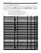
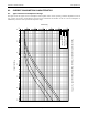
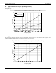
9.4. Typical Crystal Drive Current
This graph shows the current consumption of the crystal driver over a range of crystal frequencies and crystal settings, all
data points above 25 MHz were obtained by using a resonator since the driver does not perform 3
rd
harmonic overtone
driving required for crystals over 25 MHz.
0 5 10 15 20 25 30 35 40 45 50
0.2
0.4
0.6
0.8
1.0
1.2
1.4
Typical Crystal Drive Current (Vdd = 3.3 V, Ta = 25° C)
Current (mA)
xtal1
xtal2
xtal3
Frequency (MHz)
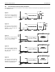
9.5. Cog and I/O Pin Relationship
The figure below illustrates the physical relationship between the cogs and I/O pins. While there can be a 1 to 1.5 ns
propagation delay in output transitions between the shortest and longest paths, the purpose of the figure is to illustrate the
length of leads and their associated parasitic capacitance. This capacitance increases the amount of energy required to
transition a pin’s state and therefore increases the current draw for toggling a pin. So, the current consumed by Cog 7
toggling P0 at 20 MHz will be greater than Cog 0 toggling P7 at 20 MHz. The amount of current consumed by transitioning a
pin’s state is dependent on many factors including: temperature, frequency of transitions, external load, and internal load. As
mentioned, the internal load is dependent upon which cog and pin are used. Internal load current for room temperature
toggling of a pin at 20 MHz for a Propeller in a DIP package varies on the order of 300 µA.
cog 0 cog 1 cog 2 cog 3 cog 4 cog 5 cog 6 cog 7
P7
P8
P6
P5
P10
P9
P24
P23
P25
P26
P21
P22
P15
P0
P16
P31