Model 5250 v.
IMPORTANT SAFETY INSTRUCTIONS The lightning flash with the arrowhead symbol within an equilateral triangle is intended to alert the user to the presence of “dangerous voltage” inside the product that may constitute a risk of electric shock. The exclamation point within an equilateral triangle is intended to alert the user to the presence of important operating and maintenance instructions in the literature accompanying the product. TO REDUCE THE RISK OF ELECTRIC SHOCK, DO NOT REMOVE COVER.
TABLE OF CONTENTS Introduction. . AC Voltage.. 1 . . . . . . . . . . . . . . . . . . . . . . . . . . . . . . . . . . . . . . . . . . . . . . . . . . . 2 . . . . . . . . . . . . . . . . . . . . . . . . . . . . . . . . . . . . . . . . . . . . . . . . . . . . 3 . . . . . . . . . . . . . . . . . . . . . . . . . . . . . . . . . . . . . . . . . . 3 . . . . . . . . . . . . . . . . . . . . . . . . . . . . . . . . . . . . . . . . . . . . . . . . 3 Ventilation Requirements.. Rack Mounting. .
2 INTRODUCTION Congratulations and thank you for your purchase of this precision Parasound audio component. The Parasound Model 5250 v.2 is the latest generation of popular and proven audio power amplifiers dating back to 1981. It has been designed for a wide variety of applications, establishing a new standard for audio performance, user-friendliness and utility in custom installations. The versatility of the Model 5250 v.
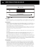
ac voltage, installation and rack mounting 115v – 230v AC Voltage 110–120V is the typical AC voltage in North America; most other countries supply 220–240V. The 5250 v.2 is internally wired for either 115V or 230V, according to where you purchased it and the voltage that is marked on its carton. If you plug a unit that is wired for 115V into a 230V outlet it can damage it. Note: Only a qualified repair technician should make AC voltage conversions.
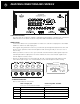
4 Rear Panel Connections and Controls Connection Precautions Disconnect the AC cord before making or changing any input, trigger, or speaker wire connections. Make sure there is no strain or tension on any wires that could cause them to pull loose Audio In Jacks Connect the cables from your preamplifier or multi-room controller’s output jacks to the Model 5250 v.2’s channel 1–5 audio Input jacks. We suggest using channels 1 and 2 for your left front (L) and right front (R) channels.
Rear Panel Connections and Controls continued Gain Control Knobs for Channels 1–5 The Gain control knobs should be left at the 12 o’clock Normal setting for most applications. When a Gain control knob is set to Normal the gain for that channel is 29. This is the THX Ultra2 Reference level where 1V input = 28.28V output. 28.28V driving an 8 speaker = 100 watts.
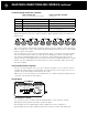
6 Rear Panel Connections and Controls continued 7.1 Channel Speaker Connections (continued) 5250 v.2 Input jack 5250 v.
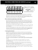
Rear Panel Connections and Controls continued When either automatic turn on is selected the Model 5250 v.2 front panel Power button is disabled so that on/off is determined solely by the triggering preamp or system controller. Man (Manual) Position When the Turn On Options switch is in its MAN (manual) position, the Turn On Options function is disabled and the Model 5250 v.2 must be turned on and off manually by pressing the Power button on its front panel. Auto - 12V Position Your 5250 v.
8 Front Panel Buttons And Display Power Button Press the Power button once to turn the Model 5250 v.2 on, press it again to turn it off. The Power button is inoperative when the Turn On Options switch on the rear panel is set to Audio or 12V. Protect Indicator The Protect indicator will illuminate red if the Model 5250 v.2 experiences an external fault condition and the unit will stop playing. This prevents possible damage to the unit from continued operation.
Front Panel Buttons And Display continued / Problems and Remedies Channel 1 2 3 4 5 Status Indicators 1 2 3 4 5 will illuminate green when the Model 5250 v.2 power is on and it is operating normally. The 1 indicator will not light if a fault is only in channel 1; the 2 indicator will not light if a fault is only in channel 2, and so on. None of the five indicators will illuminate if there is a general fault or if the temperature is too high. Problems and Remedies Maintaining Your Model 5250 v.
10 if you require assistance Call your Parasound dealer first. If the dealer can’t help you with your problem we encourage you to call Parasound’s Technical Service Department, toll-free at 415 397-7100, Monday – Friday, 8am – 4pm Pacific time. We can suggest other diagnostic tests you can easily perform. If we determine that your Model 5250 v.
parasound model 5250 v.2 Specifications Continuous RMS Power Output Inter-Channel Crosstalk 20 Hz – 20 kHz, Five Channels Driven 85 dB, 1 kHz 250 watts x 5, 8 Ω 73 dB, 10 kHz 385 watts x 5, 4 Ω 67 dB, 20 kHz Current Capacity Damping Factor 45 amps peak per channel Frequency Response Over 150 at 20 Hz Turn On Options – DC 20 Hz – 50 kHz, +0/-3 dB, 1 watt Dynamic Headroom 9 – 12V, 15 mA Turn On Options – Audio 1.6 dB 1.
12 CONNECTION AND SETUP NOTES Notes:
CONNECTION AND SETUP NOTES Notes: 13
Parasound Products, Inc., 2250 McKinnon Avenue, San Francisco, CA 94124 Customer Service 415-397-7100 / Fax 415-397-0144 Technical Dept. service@parasound.com www.parasound.com rev 0.92 ©2010 Parasound Products, Inc.