A 31 Three Channel Amplifier OWNER’S GUIDE
Important Safety Instructions The lightning flash with the arrowhead symbol within an equilateral triangle is intended to alert the user to the presence of “dangerous voltage” inside the product that may constitute a risk of electric shock. The exclamation point within an equilateral triangle is intended to alert the user to the presence of important operating and maintenance instructions in the literature accompanying the product. TO REDUCE THE RISK OF ELECTRIC SHOCK, DO NOT REMOVE COVER.
Table of Contents Introduction . . . . . . . . . . . . . . . . . . . . . . . . . . . . . . . . . . . . . . . . . . . . . . . . . Placement and Ventilation Guidelines . . . . . . . . . . . . . . . . . . . . . . . . . . . . . . 5 . . . . . . . . . . . . . . . . . . . . . . . . . . . . . . . . . . . . . . . . . . . . . 5 . . . . . . . . . . . . . . . . . . . . . . . . . . . . . . . . . . . . . . . . . . . . . . .
INTRODUCTION Thank You for Choosing Parasound Your new Parasound Halo A 31 power amplifier has been designed with the most advanced, proven class A/AB amplifier technology. The A 31 is built to extremely strict quality and performance standards for which Parasound is renowned. We’re proud to offer you this exceptional audio component that will bring you many years of enjoyment and dependability.
Unpacking Your A 31 & Placement Guidelines Unpacking Your A 31 Carefully remove your A 31 from its shipping carton and locate the enclosed accessories: • AC power cord • Two trigger wires, one with 3.5 mm mini plugs, one with a 2.5mm and a 3.5mm mini plug While you are unpacking your A 31, inspect it thoroughly for possible shipping damage and tell your Parasound dealer immediately if you find any evidence of shipping damage.
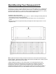
Rack Mounting Your Parasound A 31 To mount the A 31 into a 19" wide equipment rack, you must first attach its two “L” shaped rack mount brackets (included). With its four feet removed, the A 31 chassis and front panel height occupies four rack spaces (7" or 176 mm). When mounting equipment below the A 31, you will also need to allow about 1⁄8" below the unit for the bottom chassis screws. To attach the rack mount brackets: • Remove the three screws from each side of the A 31.
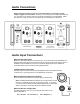
Audio Connections Always disconnect the AC cord to your A 31 before making or changing any input, output or trigger wire connections. Inserting or removing an input or output cable while the A 31 is turned on can result in a blast of sound that can damage your loudspeakers. Make sure there is no strain or tension on any cables that could cause them to pull loose. Audio Input Connections Balanced XLR Input Jacks Balanced connections will give you the best sound.
Speaker Connections Speaker Terminals The A 31 speaker terminals accept speaker wires with banana plugs, spade connectors or bare wire. Refer to “Bare Wire Speaker Ends” in the Technically Speaking section for information about bare wire termination. Correct Speaker Polarity is Important Polarity refers to + and – connections. Speaker wires are coded with color, printing or a ridge on the insulation on one of the leads so you know which lead was connected to the + and – terminals at the other end.
Gain Control Settings The Gain control knobs should be left at the 12 o’clock Normal/THX setting for most applications. When a Gain control knob is set to Normal the gain for that channel is 29. This is the THX Ultra2 Reference Level where 1V input = 28.28V output. (28.28V driving an 8Ω speaker equals 100 watts.) If you are unsure where to set the Gain control knobs it is best to start with them in the Normal position and only change them if needed, as described below.
Turn On Options For convenience, there are three ways the A 31 can be turned on and off: • Manually, by pressing the On-Off (Power) button on the front panel. • Automatically, when an audio signal is present at any of the audio Input jacks. • Automatically, when a suitable trigger voltage is applied to the 12V input jack.
12 Volt Jacks 12V In Jack The A 31 12V input uses a 3.5mm jack (mono). To use the 12V trigger, insert the trigger wire plug into this jack and the plug at the wire’s other end into the AV receiver or preamp’s 12V output jack. We have included a 3.5mm to 3.5mm trigger wire as well as a 3.5mm to 2.5mm trigger wire. Note: If the controller’s trigger output is a + and – terminal, you can cut the 3.5mm plug off one end of the included trigger wire and attach the bare wires to these terminals.
Front Panel Operation On-Off Button Push once to turn on the A 31. When the A 31 is turned on the blue glow around the On-Off button will be brighter, the red P badge will glow brighter and then the 3 channel indicators will illuminate blue. Push again to turn off the A 31. The front panel On-Off button will be disabled when the Turn On Options switch is set to Audio or 12V.
Technically Speaking Balanced and Unbalanced Lines Recording and broadcast studios use balanced connections exclusively because of their inherent ability to reject noise and hum, thus assuring the best sound. Certain high quality preamplifiers and surround controllers built for residential use utilize balanced connections with XLR jacks for the same reasons.
1. Your Cable TV or Satellite receiver box might require a Cable TV ground isolator. 2. Use balanced input lines with your Parasound A 31. (See Balanced and Unbalanced Lines in this section). 3. When rack mounting, always use the insulated “shoulder” washers. These break the ground loops caused by metal-to-metal contact between the rack, the components, and their rack-mount bolts. Extra washers are available from rack manufacturer Middle Atlantic Products, www.middleatlantic.com.
times and under all conditions. It also reduces inter-channel crosstalk that can blur the sound and impair the correct sense of where instruments, dialogue and effect are positioned. Each channel’s +/- 80 Vdc B+ and B- supply rails use high-speed rectifier diodes and four enormous 8,200 uF electrolytic filter capacitors, chosen for their low Equivalent Series Resistance (ESR) and dielectric absorption.
The Output Stage The amplifier’s sonic characteristics are established by its input and driver stages. Now, the sole job of its output stage is to deliver the enormous current and voltage from its power supply to the speakers. Bipolar output transistors are better than MOSFETS in the output stage because of their higher safe operating area (SOA) and inherent ruggedness.
Total Protection - Current Overload Specialized current-sensing transistors are connected to the output stages of the A 31 to constantly monitor the current flow through the output transistors. If the current drawn by this stage exceeds a predetermined safe level due to a load impedance below 1 ohm or a short circuit at the speaker terminals, the output relay will open immediately to prevent any of the output transistors or other parts from failing.
Are You Having Difficulty? Repair or Service Call your Parasound dealer first. If the dealer can’t help you with your problem we encourage you to call Parasound’s Technical Service Department at 415 397 7100, Monday - Friday, 8am - 4pm Pacific Time. We can suggest other diagnostic tests you can easily perform.
Specifications Power Output - All Channels Driven Input Sensitivity for 28.
Parasound Products, Inc. 2250 McKinnon Ave, San Francisco, CA 94124 415-397-7100 / Fax 415-397-0144 www.parasound.