
Owner's Manual


10
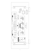
Speaker Connections for Bridged Mode
When operating in bridged mono mode a JC 5 should only power a single 8 ohm speaker.
Connect the speaker’s positive (+) speaker wire to the JC 5’s right channel positive (+) speaker terminal.
Connect the speaker’s negative (-) wire to the JC 5’s left channel positive (+) speaker terminal.
Correct + and - speaker polarity for bridged mode is shown below the JC 5 speaker terminals.
Bi-Amping is Often Superior to Bridged Mode
Bridging offers a massive power increase but It is often more power than your speakers need or can
safely handle. Bi-amping is an alternative to bridging and many people report greater sonic
improvements. Like bridging, bi-amping will require a JC 5 amplifier for each speaker.
Note: Bi-amping in this context is technically “passive bi-amping” so an external electronic crossover is
not required. The speaker LF and HF terminals still connect to the speaker’s passive crossover
circuits, the difference being that with passive bi-amping the LF and HF crossovers are powered
separately.
Connecting speaker wires for Bi-amping
Bi-amping requires speakers with separate LF (Low Frequency) and HF (High Frequency) input
terminals with removable metal straps or wires. (Some KEF speakers use a rotary switch to join or
separate the HF and LF sections). The left channel of the first JC 5 will power the LF section of one
speaker and this same JC 5’s right channel will power the HF section of the same speaker. The
second JC 5 will connect the same way to the right channel speaker’s LF and HF inputs. When bi-
amping both JC 5’s Bridged switches must be set to their Normal (Stereo) position.
Setting up the input wires for Bi-amping
The JC 5 has an RCA Loop Output jack for each channel. These looping outputs allow the input
signal from one channel to be daisy-chained to the other channel’s RCA Input jack. When bi-amping
you will connect a standard RCA cable from the loop output of the Left channel to the Input RCA jack
of the right channel. If you wish to connect your preamp with balanced XLR connections you will need
to purchase a pair of XLR “Y” cables. You cannot use a combination of a balanced XLR input and
RCA Loop Out to the other channel’s input because the balanced connections will play 6dB louder
than the RCA connections.
Note: Both amplifiers left and right channel gain controls should be set at the same position.
Speaker Connections
Speaker Terminals
The JC 5 speaker terminals accept speaker wires terminated with banana plugs, spade connectors or up to 8
AWG bare wire.
Bare Speaker Wire Ends
If you plan to connect your speaker cables with bare wire ends, use a wire stripper to remove just enough
insulation to expose a 12" (13 mm) length of bare wire. You can insert the stripped wire into the hole that
goes vertically through each terminal’s metal post. Before inserting the wire, twist its bare strands tightly to
prevent any of the individual strands from making contact across the red plus and black minus speaker
terminals. If you have a soldering iron, you can “tin” (apply a small amount of molten solder) to each stripped
bare wire to prevent it from unraveling, fraying and oxidizing.