Model 2125 v.
Important Safety Instructions The lightning flash with the arrowhead symbol within an equilateral triangle is intended to alert the user to the presence of ―dangerous voltage‖ inside the product that may constitute a risk of electric shock. The exclamation point within an equilateral triangle is intended to alert the user to the presence of important operating and maintenance instructions in the literature accompanying the product. TO REDUCE THE RISK OF ELECTRIC SHOCK, DO NOT REMOVE COVER.
Table of Contents Introduction . . . . . . . . . . . . . . . . . . . . . . . . . . . . . . . . . . . . . . . . . . . . . . . . . . Placement and Ventilation Guidelines Rack Mounting 4 . . . . . . . . . . . . . . . . . . . . . . . . . . . . . . 5 . . . . . . . . . . . . . . . . . . . . . . . . . . . . . . . . . . . . . . . . . . . . . . . . 5 AC Mains Voltage . . . . . . . . . . . . . . . . . . . . . . . . . . . . . . . . . . . . . . . . . . . . . Rear Panel Connections and Controls 6 . . . . . .
INTRODUCTION Thank You for Choosing Parasound Your new Parasound Model 2125 v.2 power amplifier has been designed with proven class AB amplifier technology. The Model 2125 v.2 is built to extremely strict quality and performance standards for which Parasound is renowned. We’re proud to offer you this exceptional audio component that will bring you many years of enjoyment and dependability. We designed your new Model 2125 v.
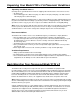
Unpacking Your Model 2125 v.2 & Placement Guidelines Unpacking Your Model 2125 v.2 Carefully remove your Model 2125 v.2 from its shipping carton and locate the enclosed accessories: • AC power cord • Two 12V DC trigger wires with mono plugs, one with 3.5 mm (1/8‖) mini plugs, one with a 2.5mm sub-mini plug and a 3.5mm mini plug While you are unpacking your Model 2125 v.
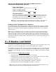
AC Mains Voltage NOTE: Before you plug this amplifier into an AC mains outlet: 115v - 230v AC Voltage Selector Switch This switch is found on the chassis rear panel. The 115V position of this switch is correct for North America; most other regions require setting it to 230V. Make sure the 115/230V switch is set for the correct AC line (mains) voltage before you connect the Model 2125 v.2’s power cord and before you install it. The unit may be seriously damaged if this switch is set incorrectly.
R (Right) and L (Left) Level Knobs To increase the listening level for each channel, turn its Level knob clockwise. To decrease the listening level turn it counter-clockwise. The 2125 has a total gain of 28 dB so that its volume levels are compatible with other channels in your theater if they are driven by a THX-certified amplifier, up to the point where the THX-certified amplifier might play a bit louder because of its higher power output.
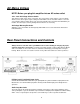
Speaker Connections Speaker Terminals There are separate speaker terminals for two pairs of speakers, labeled Speaker Pair A and Speaker Pair B. The speaker terminals accept speaker wires with banana plugs, spade connectors or bare wire. Correct Speaker Polarity is Important Polarity refers to + and – connections. Speaker wires are coded with color, printing or a ridge on the insulation on one of the leads so you know which lead was connected to the + and – terminals at the other end.
How to set the Speaker Load switch when the Model 2125 v.2 is configured for Bridged Mono operation: Single 8 Ohm Speaker In this case the Speaker Load switch should be set to 4-8Ω. Single 4 or 6 Ohm Speaker In this case the Speaker Load switch must be set to 2-3Ω. Two 8 Ohm Speakers In this case the Speaker Load switch must be set to 2-3Ω.
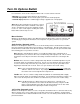
Turn On Options Switch For convenience, there are three ways the Model 2125 v.2 can be turned on and off: • Manually, by pressing the Power button on the front panel. • Automatically by Audio, when an audio signal is present at the audio Input jacks. • Automatically by 12V, when a suitable trigger voltage is applied to the 12V input jack.
12 Volt Input Jacks The Model 2125 v.2 12V input uses a 3.5mm jack (mono). To use the 12V trigger, insert the trigger wire plug into this jack and the plug at the wire’s other end into the AV receiver or preamp’s 12V output jack. We have included a 3.5mm to 3.5mm trigger wire as well as a 3.5mm to 2.5mm trigger wire. Note: If the controller’s trigger output is a + and – terminal, you can cut the 3.5mm plug off one end of the included trigger wire and attach the bare wires to these terminals.
Front Panel Operation Power Button Press the Power button once to turn the Model 2125 v.2 on. Press it again to turn it off. When the unit is powered on the L and R indicators should illuminate green. The Power button is inoperative when the Turn On Options switch is set to Audio or 12V. A and B Speaker Select Buttons These buttons turn on the speaker pairs connected to the corresponding Speaker Pair A and B terminals.
Problems and Remedies Unit Will Not Turn On • Check the setting of the Turn On Options switch. (The front panel Power button will be disabled if the switch is set to Audio or 12V). First try the Manual position and see if the unit will turn on by pressing the front panel Power button. • If using Audio Turn on, try increasing the sensitivity of the audio trigger by setting the Turn On Option switch to the ―Quieter‖ position. • If using Audio Turn on and you need the Model 2125 v.
Are You Having Difficulty? Repair or Service Call your Parasound dealer first. If the dealer can’t help you with your problem we encourage you to call Parasound’s Technical Service Department at 415 397 7100, Monday - Friday, 8am - 4pm Pacific Time. We can suggest other diagnostic tests you can easily perform. If we determine that your Model 2125 v.
Specifications Power Output – (RMS power, 20 Hz – 20 kHz) Input Impedance - 33 k Ω All Channels Driven 150 watts x 2, 8Ω 225 watts x 2, 4Ω 225 watts x 2, 2Ω (Load switch set to 2-3Ω) Input Sensitivity 1 V in for 28.
Parasound Products, Inc. 2250 McKinnon Ave, San Francisco, CA 94124 415-397-7100 / Fax 415-397-0144 www.parasound.