Power Protect R L Mo d e l 2 7 5 T w o C h a n n e l Hi Temp A m p l i f i e r A Model 275 Two Channel Power Amplifier Two Channel Amplifier OWNER’S GUIDE B
IMPORTANT SAFETY INSTRUCTIONS The lightning flash with the arrowhead symbol within an equilateral triangle is intended to alert the user to the presence of “dangerous voltage” inside the product that may constitute a risk of electric shock. The exclamation point within an equilateral triangle is intended to alert the user to the presence of important operating and maintenance instructions in the literature accompanying the product. TO REDUCE THE RISK OF ELECTRIC SHOCK, DO NOT REMOVE COVER.
TABLE OF CONTENTS Unpacking and Accessories . . . . . . . . . . . . . . . . . . . . . . . . . . . . . . . . . . . . . . . . . . 115v – 230v AC Selector Switch Ventilation Requirements . Rack Mounting 1 . . . . . . . . . . . . . . . . . . . . . . . . . . . . . . . . . . . . . . . . 3 . . . . . . . . . . . . . . . . . . . . . . . . . . . . . . . . . . . . . . . . . . 3 . . . . . . . . . . . . . . . . . . . . . . . . . . . . . . . . . . . . . . . . . . . . . . . . .
2 INTRODUCTION Congratulations and thank you for your purchase of this precision Parasound audio component. The Parasound Model 275 is the latest generation of popular and proven audio power amplifiers dating back to 1981. It has been designed for a wide variety of applications, establishing a new standard for audio performance, user-friendliness and utility in custom installations.
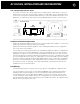
AC VOLTAGE, INSTALLATION AND RACK MOUNTING 115v - 230v AC Voltage Selector Switch This switch is found on the chassis rear panel. The 115V position of this switch is correct for North America; most other regions require setting it to 230V. Make sure the 115/230V switch is set for the correct AC line (mains) voltage before you connect the Model 275’s power cord and before you install it. The unit may be seriously damaged if this switch is set incorrectly. Protective Cover L ove Cover. No Service Personnel.
gger 4 REAR PANEL CONNECTIONS AND CONTROLS Connection Precautions Disconnect the AC cord before making or changing any input, trigger, or speaker wire connections. Make sure there is no strain or tension on any wires that could cause them to pull loose. High Pass Filter 275 Two Channel Amplifier L Parasound Products, Inc.
p REAR PANEL CONNECTIONS AND CONTROLS continued 5 High Pass Filter Switch The High Pass filter can improve the sound in virtually any installation. It’s called a “high pass” filter because it permits signals higher than 20 Hz and 40 Hz to pass, while preventing signals below these frequencies from passing.
REAR PANEL CONNECTIONS AND CONTROLS continued 6 Correct Speaker Polarity is Important As you connect the speaker wires, you can see that the insulation on one of the two wires in each pair has either printing or a raised ridge. The marking lets you know which wire you connected to the positive speaker terminal at its other end. Make sure the + wire you attach to each Model 275 + speaker terminal is attached to the + terminal of the speaker for that channel.
REAR PANEL CONNECTIONS AND CONTROLS continued For a single pair of 4 ohm or 8 ohm speakers the Load Impedance switch may be set to its 4-8 Ohms position. The Load Impedance Switch must be set to 2-3 ohms whenever the load will be lower than 4 ohms. Speaker loads below 4 ohms impedance can cause the Model 275 to overheat rapidly and cause audible distortion. These are examples that require the 2-3 ohms setting. 1. Driving two pairs of speakers whose impedances you don’t know. 2.
8 REAR PANEL CONNECTIONS AND CONTROLS continued 275 Two Channel Amplifier L Parasound Products, Inc. San Francisco, CA U S A Manual Audio Sens 12V Trigger In Audio 12V Max High Pass + Flat 20Hz Ground Loop R Min Mono Lift Norm Auto Turn On + In Loop Stereo Bridgi Level Note: If the controller’s trigger output is a + and - terminal, you can cut the 2.5mm plug off one end of the included trigger wire and attach the bare wires to these terminals.
FRONT PANEL BUTTONS AND DISPLAY 9 Power Button Press the Power button once to turn the Model 275 on, press it again to turn it off. The Power button is inoperative when the Auto Turn On switch is set to Audio or 12V. Note: It is normal for the 275 Protect indicator to flash briefly right after turn on.
10 PROBLEMS AND REMEDIES Maintaining Your Model 275 Your Parasound Model 275 power amplifier requires no periodic maintenance other than the knowledge that you are bragging about it to your friends. It has no user-serviceable parts inside. To avoid the risk of electric shock, do not remove its top cover. The exterior can be cleaned with a soft cloth pre-moistened only with a few drops of water or glass cleaner. Troubleshooting No sound • • • • • • • Check that AC is live.
IF YOU REQUIRE ASSISTANCE Call your Parasound dealer first. If the dealer can’t help you with your problem we encourage you to call Parasound’s Technical Service Department, toll-free at 1-866-770-8324, Monday - Friday, 8am - 4pm Pacific time. We can suggest other diagnostic tests you can easily perform.
12 PARASOUND MODEL 275 SPECIFICATIONS Continuous RMS Power Output 20 Hz – 20 kHz, Both Channels Driven 75 watts x 2, 8 Ω 120 watts x 2, 4 Ω 120 watts x 2, 2 Ω Continuous RMS Power Output 20 Hz – 20 kHz, Bridged Mono 200 watts, 8 Ω 200 watts, 4 Ω Current Capacity 20 amps peak per channel Frequency Response 20 Hz - 50 kHz, +0/-3 dB, 1 watt Dynamic Headroom 1.3 dB Total Harmonic Distortion 0.035% at full rated output 0.025% at average listening levels IM Distortion 0.
CONNECTION AND SETUP NOTES Notes: 13
We invite you to visit www.parasound.com for the most up-to-date information on your unit and to find out about other Parasound products. Learn why Parasound has been a quality and value favorite of magazine reviewers, sound professionals and listeners like you since we were founded in 1981. Parasound Products, Inc. 950 Battery Street, San Francisco, CA 94111 Customer Service 415-397-7100 / Technical Dept. 415-675-7272 / Fax 415-397-0144 www.parasound.com rev 0.91 ©2005 Parasound Products, Inc.