
Two Channel Power Amplifier OWNER'S GUIDE 275


High Pass Filter Switch
The High Pass filter can improve the sound in virtually any installation. It’s called a “high pass”
filter because it permits signals higher than 20 Hz and 40 Hz to pass, while preventing signals
below these frequencies from passing.
•
The Flat switch position disconnects the filter and the 275’s frequency response is flat.
•
The 20 Hz switch position filters out frequencies below 20 Hz. Your speakers have greater
dynamic range and far less distortion when they don’t receive frequencies which are lower than
they can reproduce. Likewise, the 275 operates more efficiently when it’s not called upon to
amplify frequencies which the speakers can’t reproduce. Because the 20 Hz filter has a steep
18 dB per octave slope, it is essentially a sub-sonic filter, and you probably won’t notice any
loss of bass unless you’re using very large speakers.
•
The 40 Hz switch position filters bass below 40 Hz at 18 dB per octave. This is ideal when the
275 is driving in-wall or in-ceiling speakers because very few of them can reproduce very much
bass below 40 Hz. You’ll enjoy much cleaner sound and higher undistorted volume levels. Not
having to amplify bass that’s inaudible with your speakers is another way the 275 will run cooler.
Note: Autoformer-type passive volume controls are highly reactive loads that are known to cause
amplifier malfunction. The 20 Hz or 40 Hz filter settings enable the 275 to drive them with ease.
Speaker Connections
There are separate speaker terminals for two pairs of speakers, labeled Speaker Pair A and
Speaker Pair B.
Each - and + speaker terminal will accept bare speaker wire up to AWG 12, a wire terminated
with a
1
⁄4” spade lug, or with a single banana plug; dual banana plugs which are
3
⁄4” (19mm) apart
may be used for each speaker.
If you use bare wires, remove only enough insulation, about
1
⁄2” (12mm) for each exposed bare
wire to insert through the small hole in the side of the binding post. Before inserting a bare
wire, twist the strands tightly between your fingers to prevent strays that might touch the chas-
sis or another terminal and cause a short circuit. If you have soldering experience you may want
to “tin” the stripped bare wire with solder for a cleaner termination and to prevent the wire
from oxidizing.
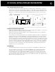
REAR PANEL CONNECTIONS AND CONTROLS continued
5
WARNING: To Prevent Fire Or Shock Hazard,
Do Not Expose This Unit To Rain Or Moisture.
AC 115V/60Hz
AC 230V/50Hz
Speaker Pair A
L
R
Mono
Manual Audio Sens
Max Min
12V Trigger
Ground
Lift
Norm
Mono
Stereo
4-8
Ohms
2-3
Ohms
230V
50Hz
115V
60Hz
20Hz 40HzFlat
Audio
Auto Turn On Loop Level
Bridging
In
12V
In Loop
R
Mono
+
+
AC 115V/60Hz
AC 230V/50Hz
Power Consumption: 300W
AC
Voltage
Load
Impedance
275 Two Channel Amplifier
Parasound Products, Inc.
San Francisco, CA U S A
CAUTION: To Prevent Electric Shock, Do Not Remove Cover. No
User-Serviceable Parts Inside. Refer Servicing To Qualified Service Personnel.
L
High Pass Filter
Speaker Pair B
L
R
Mono
Speaker Pair A
L
R
Mono
Speaker Pair B
L
R
Mono