P 3 Preamplifier Owner’s Guide
THANK YOU! Congratulations and Thank You for Choosing Parasound Your new Parasound P 3 Preamplifier presents the latest advancements in audio technology. The P 3 is built to the strict quality and performance standards set by Parasound. We’re proud to offer you this exceptional audio component that will bring many years of enjoyment and dependability. Here at Parasound, we design our products to perform to a higher level of flexibility and sonic performance than you may have expected.
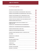
TABLE OF CONTENTS P 3 Preamplifier 1 UNPACKING AND PLACEMENT GUIDELINES FOR THE P 3 __________________________________________________________________________________________ 2 CONNECTING A SOURCE COMPONENT TO THE BALANCED DIRECT 1 INPUTS ON THE P 3 __________________________________________________________________________________________ 3 CONNECTING A SOURCE COMPONENT TO THE UNBALANCED DIRECT 1 INPUTS ON THE P 3 __________________________________________________________________________________________ 4
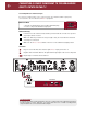
1 UNPACKING AND PLACEMENT GUIDELINES FOR THE P 3 Unpacking Your P 3 Carefully unpack your P 3 from the shipping carton and remove all the enclosed accessories: • Remote control with two AAA batteries • Detachable AC cord • Two Trigger control wires with a 2.5 mm sub-mini plug on each end. While you are unpacking your new preamplifier, inspect it thoroughly for possible shipping damage. If you see any, contact your Parasound dealer right away.
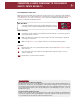
CONNECTING A SOURCE COMPONENT TO THE BALANCED DIRECT 1 INPUTS ON THE P 3 2 Left and Right Direct 1 Input Jacks Balanced connections will give you the best sound. If your source components have balanced XLR output jacks, we recommend that you connect them to these inputs. Refer to the Balanced and Unbalanced Lines in the Technically Speaking section for additional information about why we recommend using balanced lines.
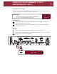
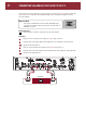
3 CONNECTING A SOURCE COMPONENT TO THE UNBALANCED DIRECT 1 INPUTS ON THE P 3 Left and Right Direct 1 Unbalanced Inputs If your best-sounding audio source component has only unbalanced RCA output jacks, connect them to the P 3 unbalanced Direct 1 input jacks.
CONNECTING A SOURCE COMPONENT TO THE P 3 UNBALANCED DIRECT 2 INPUTS 4 Direct 2 Unbalanced Input Jacks The P 3 Unbalanced Direct 2 input jacks are for your next-best-sounding source component if the Direct 1 input jacks are already connected to another source.
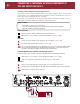
5 CONNECTING A TURNTABLE OR OTHER COMPONENT TO THE AUX INPUTS ON THE P 3 Connecting a Source Component to the Aux Inputs on the P 3 The P 3 has a single Aux input, but two pairs of Aux jacks for either a phono or a line level source. The Aux Select switch determines if you’ll hear the source connected to the Aux-Phono jacks or the source connected to the Aux-Line jacks.
CONNECTING OTHER SOURCE COMPONENTS TO THE CD AND TUNER INPUTS ON THE P 3 6 Connect the outputs of your CD player, tuner, or any other line level source to the CD and Tuner jacks. All of the line level inputs are electrically identical. What You’ll Need For Each Input Connection: Left • One pair of shielded interconnect cables with RCA plugs • A source component with RCA output jacks Right RCA Plugs Before Connecting Remove power to all the components in your audio system.
7 CONNECTING AN ANALOG TAPE DECK TO THE P 3 Connect the input and output from your analog tape recorder to the Tape Play and Rec (Record) jacks of the P 3. See Tape Record and Play Circuitry in the Technically Speaking section for more information. What You’ll Need: Left • Two pairs of shielded interconnect cables with RCA plugs • An analog recording component such as a cassette deck or a MiniDisc recorder Right RCA Plugs Before Connecting Remove power to all the components in your audio system.
CONNECTING AN EXTERNAL SIGNAL PROCESSING COMPONENT TO THE P 3 EXTERNAL LOOP JACKS 8 You can connect signal-processing equipment such as a frequency-shaping equalizer into the signal path of the P 3 via its External Loop Connections. See External Loop In/Out Connections in the Technically Speaking section for more information.
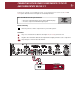
9 CONNECTING THE P 3 TO THE BALANCED INPUTS ON YOUR POWER AMPLIFIER For best sound performance, use the P 3 Balanced Line Output connections if your power amplifier is equipped with balanced inputs. What You’ll Need: Male • One pair of balanced interconnect cables with XLR plugs • An amplifier with balanced XLR input jacks Female XLR Connectors Before Connecting Leave the AC cord disconnected until you have made all connections to prevent any surprise burst of sound.
CONNECTING THE P 3 TO THE UNBALANCED INPUTS ON YOUR POWER AMPLIFIER 10 Use these outputs if your power amplifier does not have balanced input connectors or if you prefer to use unbalanced connections. What You’ll Need: Left • One pair of shielded interconnect cables with RCA jacks • A power amplifier with unbalanced input jacks Right RCA Plugs Before Connecting Remove power to all the components in your audio system.
11 CONNECTING AN INFRARED REPEATER SYSTEM TO THE P 3 The External Remote Input jack is for a wired infrared repeater system or system controller. It eliminates the need for a stick-on front panel IR flasher. There is also a Loop Out jack to loop or “daisy chain” to an additional infrared remote-controlled component.
TURNING ON THE P 3 WITH AN EXTERNAL TRIGGER VOLTAGE The P 3 can be turned on automatically when a trigger voltage is received from an external DC voltage source such as a system controller. What You’ll Need: • A trigger cable with 2.5 mm sub-mini plugs (provided) • A component with an external +9Vdc to +12Vdc trigger voltage 2.5 mm sub-mini plug Before Connecting Remove power to all the components in your audio system. To Connect 1 Plug one end of this cable into the 12V Trigger Input jack of the P 3.
13 TRIGGERING ON ANOTHER COMPONENT FROM THE P 3’S TRIGGER OUTPUT JACK The 12V Trigger Output jack generates its own +12 Vdc voltage whenever the P 3 is turned on so it can trigger other components such as a Parasound power amplifier. This output will provide up to 200 mA of current to trigger an external component. What You’ll Need: • A second trigger cable with 2.5 mm sub-mini plugs (provided) • A component that can be triggered with an external +9 Vdc to +12 Vdc trigger voltage 2.
RS232 CONTROL 14 The P 3 External Control connector is used only if you have a computer-based system controller. The P 3 is compatible with most system controllers. RS232 codes for Parasound units can be downloaded from www.parasound.com. Connecting a Controller to the RS232 Port of the P 3 What You’ll Need: • A computer-based control system with RS232 serial output • An RS232 serial cable with a DB9 connector.
15 CONNECTING THE P 3 AC POWER CORD AC Power Connections We recommend plugging your P 3 into the same AC outlet or power strip used for your accompanying audio components, especially the power amplifier and source components. What You’ll Need: • An IEC 65 AC Cord (provided) • An AC outlet or power strip within reach of the AC cord Before Connecting Remove power to all the components in your audio system. To Connect 1 Plug the female end of the AC cord into the AC receptacle on the rear of the P 3.
OPERATING YOUR P 3 16 See page 19 for P 3 Front Panel and Remote Control layout Turning the P 3 On and Off You can turn the P 3 on and off with the On-Off button on its front panel, with the On and Off buttons on its remote control handset, or with an external DC source. Turning On the P 3 Press either the On-Off Button on the front panel or the On button on the remote control. Turning Off the P 3 Press either the On-Off Button on the front panel or the Off button on the remote control.
17 OPERATING YOUR P 3 continued See page 19 for P 3 Front Panel and Remote Control layout Selecting the Input Source You can select the input source by repeatedly pressing the Source button on the front panel until the desired source name appears in the status display. You can also select the desired source directly with the Source select buttons on the remote control.
OPERATING YOUR P 3 continued See page 19 for P 3 Front Panel and Remote Control layout Adjusting Bass and Treble Tone Tone Button Pressing the Tone button on the front panel or remote control turns on the tone display. The illumination around the Bass and Treble buttons will also brighten. After pressing the Tone button, you have about five seconds to make adjustments. < Bass > Buttons 1 Press the Tone button once to display the present bass boost or cut.
P 3 FRONT PANEL AND REMOTE CONTROL 19 1 2 3 4 15 5 14 6 7 13 8 9 12 11 P 3 - T 3 Remote Buttons Controls 1. On,Off 2. Tone On-Off 3. Mute On-Off 4. Source Select 5. Preset < > 6. Tuning < > 7. FM-AM Select 8. Tuner Presets 9. Enter Frequency 10. Memory & Automemory 11. Mono Select 12. Radio Data System 13. Seek < > 14. Manual < > 15. Volume Adjust P P P P T T T T T T T T T T P 3&T3 3 3 3 3 3 3 3 3 3 3 3 3 3 3 10 10 9 1 2 3 4 7 5 P 3 Front Panel 1. Phones Jack 2. On-Off 3.
TROUBLESHOOTING GUIDE Your Parasound P 3 Preamplifier requires no periodic maintenance and has no user-serviceable parts inside. To avoid the risk of electric shock, do not remove the top cover. The P 3’s exterior can easily be cleaned with a soft cloth pre-moistened only with a few drops of water or glass cleaner. Main Power Fuse If this fuse blows, please contact Parasound Technical Service for further advice.
21 SERVICING YOUR P 3 If All Else Fails –Call Us for Help Call your Parasound dealer or Parasound’s Technical Service Department toll free at 1-866-770-TECH (8324). We can often solve the problem with simple diagnostic tests you can perform yourself. If we determine that your P 3 will need further inspection or servicing, we will: a) refer you to an authorized Parasound repair center near you, or b) authorize return of the unit to us and advise you of the correct procedure.
TECHNICALLY SPEAKING 22 Balanced and Unbalanced Input Lines Direct Inputs Recording and broadcast studios use balanced connections almost exclusively because of their inherent ability to reject noise and hum, assuring the best sound. Certain high quality preamplifiers and surround controllers built for residential use utilize balanced connections with XLR jacks for the same reasons.
23 TECHNICALLY SPEAKING continued even risk overloading your speakers. You can only adjust the bass and treble controls on the front panel. However, you can compare the sound with the tone controls on or off by pressing the Tone button on the front panel or remote control. DC Trigger Input Jack The P 3 can be turned on automatically when a trigger voltage is received from an external source such as a system controller.
PARASOUND P 3 DESIGN OVERVIEW Parts Selection Audio Circuit Path Topology Every part within the P 3 is carefully chosen for its accuracy and reliability. Metal film resistors with 1% tolerance are selected for their precision and because their values don’t drift as they heat up during operation. Polypropylene and mica capacitors are used extensively for their superior linearity and low dielectric absorption. Semiconductors are selected for superior performance in their specific roles in the circuit.
25 PARASOUND P 3 SPECIFICATIONS Frequency Response 5 Hz - 55 kHz, +0/-1 dB, full output Maximum Input Level 10.5 V before clipping Total Harmonic Distortion < 0.01%, 1 kHz < 0.03%, 20 kHz Signal-to-Noise Ratio Line inputs: > 92 dB, A-weighted, full output > 84 dB, unweighted, full output Phono input: >72 dB, ref. 5 mV input IM Distortion < 0.