® ZoneMaster 4 Universal Four Channel Amplifier OWNER’S Manual
Important Safety Instructions The lightning flash with the arrowhead symbol within an equilateral triangle is intended to alert the user to the presence of “dangerous voltage” inside the product that may constitute a risk of electric shock. The exclamation point within an equilateral triangle is intended to alert the user to the presence of important operating and maintenance instructions in the literature accompanying the product. TO REDUCE THE RISK OF ELECTRIC SHOCK, DO NOT REMOVE COVER.
Parasound ZoneMaster 4 Owner’s Manual Page 3
INTRODUCTION Congratulations on your purchase of this precision audio product and thank you for selecting Parasound. We are proud to offer you this versatile amplifier, knowing that it will bring you many years of enjoyment and dependable operation. Please take a few moments to read the following instructions so you can enjoy all the benefits of your new ZoneMaster 4’s advanced performance capabilities. You can find details of the ZoneMaster 4’s specifications and advanced technology at www.parasound.com.
Table of Contents Introduction . . . . . . . . . . . . . . . . . . . . . . . . . . . . . . . . . . . . . . . . . . . . . . . . . . Placement and Ventilation Guidelines . Rear Panel Audio Connections . . . . . . . . . . . . . . . . . . . . . . . . . . . . . 6 . . . . . . . . . . . . . . . . . . . . . . . . . . . . . . . . . . . 7 Speaker Level Input Connector . . . . . . . . . . . . . . . . . . . . . . . . . . . . . . . . . . . Speaker A and B Outputs and Speaker Impedance .
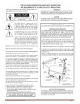
Unpacking your ZoneMaster 4 & Placement Guidelines Unpacking Your ZoneMaster 4 Carefully remove your ZoneMaster 4 from its shipping carton and locate its AC power cord and these included accessories: Two 12V trigger wires with mono 3.5mm to 3.5mm mini plugs at both ends. Left and right 1U rack mount side brackets and 4 bracket screws. Two different size screwdrivers, the larger one is for the speaker output connectors and the smaller one is for the speaker level input connector.
Rear Panel Audio Connections Channel pairs (left and right) are grouped into 2 zones. Typically each room or area is considered a zone but this will be determined by the system integrator. Always disconnect the AC cord (or turn off the master AC switch on the back) to your ZoneMaster 4 before plugging in or unplugging any connections.
Audio Output Connections The Bus Loop Out Jacks These jacks enable the audio source connected to the Bus Input jacks to pass along or “daisy chain” to an additional amplifier. The volume level and signal voltage at the Loop Out jacks is the same as the volume level and signal voltage of the sources that are connected to their corresponding Bus Input jacks.
Rear Panel Controls for Each Zone Input Select Switch The Input Select switch selects which audio source will play in that zone. There are two options: Line Input: The zone will play the audio source that is connected to the zone’s L and R Line Input jacks. Bus Input: The zone will play the audio source that is connected to either the Bus L and R RCA jacks or the L and R Speaker Level input connector. The L and R level controls will still adjust the channel levels for the zone.
Channel Level Controls Each of the four channels has its own level control. Fully counter-clockwise is all the way off and no sound will be heard from that channel. Fully clockwise is maximum volume. We made the Level control shafts very short so they are less likely to be turned unintentionally. When installed in a rack you may find it easier to use a Phillips head screwdriver to adjust the Level controls.
Turn On Options The setting of the rear panel Turn On Options Switch determines whether both zones turn on and off together or if each zone turns on and off individually. There are three positions for this switch: Manual All Pressing the Power button on the front panel will turn both zones on and off together. 12V All When a 12V trigger voltage is applied to the 12V Input jack marked “Trigger For All Zones” both zones will turn on together.
Selecting Audio Trigger or 12V Trigger by Zone When the Turn On Options switch is set to “Audio/12V By Zone” you can then set the two small 12V/Audio switches to select Audio or 12V turn on/off for each zone. For a zone that you wish to turn on and off by a 12 volt trigger, set that zone’s switch to the up position labeled “12V.” For a zone you wish to turn on and off by an audio trigger, set that zone’s switch to the down position labeled “Audio.
12 Volt Trigger Jacks by Zone 12V In Jacks The ZoneMaster 4 “12V All” jack and two individual zone jacks are 3.5mm mini jacks (mono). To use a 12V trigger, insert the trigger wire plug into the jack and the plug at the wire’s other end into the AV receiver or house controller’s 12V Output jack. We have included two trigger wires with 3.5mm mini plug at both ends. Note: If the controller’s or preamp’s 12V trigger output is a + and – terminal instead of a jack, you can cut the 3.
Front Panel Power Button and Display Power Button If the Turn On Options switch is set to the Manual position, pushing the Power button turns on all channels/zones. When turned on the ring around the Power button and the 4 channel status indicators will illuminate green. Pushing the Power button again turns off all channels/zones. If the rear panel Turn On Options switch is not set to “Manual All” the front panel power button will not operate.
Frequently Asked Questions The unit will not turn on - Check the setting of the Turn On Options switch (The front panel Power button will be disabled if the switch is set to Audio or 12V). - Check that the AC power is live. - Check that the rear panel master AC power switch is in the on position. When using the audio trigger a zone is turning off during quiet listening - Turn down the Level controls for those channels (12 O’clock is a good place to start). - See page 10 for more details.
Maintaining Your ZoneMaster 4 Your ZoneMaster 4 requires no periodic maintenance and has no user serviceable parts inside. To avoid risk of electric shock do not remove the top cover. To keep it clean use only a soft cloth moistened with a few drops of clear water or window cleaner. Never use any solvents or abrasives. Are You Having Difficulty? Warranty Repair Call your Parasound dealer first.
Specifications and Details Power Output – RMS, All Channels Driven (20 Hz - 20 kHz) 120 watts x 4 @ 8Ω 150 watts x 4 @ 4Ω or 2Ω Minimum Speaker Impedance: A+B Outputs of a Single Channel: 2 Ω Note: Continuous operation at this minimum impedance might require additional ventilation for the amplifier. Frequency Response: 20 Hz - 20 kHz, +0/-0.25 dB 5 Hz - 50 kHz, +0/-3 dB Total Harmonic Distortion < 0.05 % at typical listening levels < 1.
Installation Notes _________________________________________________________________________ ____________________________________________ ____________________________________________ ____________________________________________ ____________________________________________ ____________________________________________ ____________________________________________ ____________________________________________ ____________________________________________ ____________________________________________ _____________
Installation Notes _________________________________________________________________________ ____________________________________________ ____________________________________________ ____________________________________________ ____________________________________________ ____________________________________________ ____________________________________________ ____________________________________________ ____________________________________________ ____________________________________________ _____________
Parasound Products, Inc. 2250 McKinnon Ave, San Francisco, CA 94124 Customer Service: 415-397-7100 www.parasound.