
User's Manual
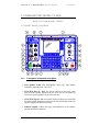


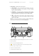


Table Of Contents
- SYSTEM FIREMASTER IV
- "Millennium Three"
- CONTENTS
- 1. Base Station - Control Unit TX5000 3
- 3.3.5 " AUTOMATIC SHOW ” Mode 55
- 3.3.6 Options in “SHOW” mode 58
- 3.3.7 Operation Notes when in "FIRE MODE" 59
- 4.8.2 Coaxial cable connection 74
- 4.8.3 RS-485 77
- 4.8.4 RS-232 79
- 5. BPK48-A Battery Pack 81
- _
- _
- 1. COMMAND UNIT MODEL TX 5000
- BASE STATION MODEL TX5000
- 1.1 FRONT-PANEL DIAGRAM
- _
- _
- 1.1.1 Front-panel commands description
- 1.2.1 Instrument case and connector description
- 1.3 Operation
- 1.5. "SHOW MANAGEMENT" Mask description
- 1.6. "TOOLS" Mask
- 1.7. "SYSTEM SETUP" Icon
- 1.8. "OLD UNITS SETUP" Icon
- 1.9. "TONE GENERATOR" Icon
- 1.10. TONE GENERATOR TESTING
- _
- 1.11. "SMPTE TEST" Icon
- 1.12. "MIDI TEST" Icon

FIREMASTER IV "
MillenniumThree
" radio shooting system User’s manual
5. FIRE Pushbutton – When pressed together with the ARM key, starts
immediately the firing of all lines with the sequence number actually
displayed. ARM and FIRE buttons, if pressed alone, have NO EFFECT.
When a sequence has been fired, in order to step to the next one (or to
allow the auto-increment function to do it automatically), it will be
necessary to release BOTH buttons. ARM or FIRE buttons, when the
keyswitch is SAFE/TEST position, can be used INDIFFERENTLY to
trigger a SYNCHRONISM tone output (see a more detailed description at
chapter 1.6 “Tools Mask”).
6. ARM Pushbutton – When pressed, the system (if the selector key is on
the FIRE position), is ARMED and ready to fire.
7. Main Antenna. Turret for the attachment of the whip antenna
supplied with the instrument. The antenna resonates at λ/4 on
40,675MHz. NOTE: use the original antenna only.
8. R.F. OUTPUT – “UHF” coaxial connector. Output for test purposes
only. It is capacitively-coupled and allows to monitor the output R.F.
signal with an oscilloscope or a frequency counter.
9. RS-485 standard SERIAL Port. 2mm plug connectors. This port is used
to connect the base Unit TX5000 to the Remote Units RX48 when a
CABLE CONNECTION is required in place of the standard RADIO link
(or to implement a mixed-type connection: CABLE+RADIO). The
connection wiring requires TWO WIRES ONLY: A and B connections
MUST be respected (i.e.: pin A of TX5000 must be connected to ALL pins
A of the RX-48 units and pin B to ALL corresponding pins B of the RX-
48 units. Only the LAST RX48 unit must be LOADED with a terminating
120ohm resistor placed between A and B.
10. TONE OUT: RCA-type connector (red). Generates an audio synchronism
tone: it can be recorded along with the musical base in order to
synchronize the FIRE command.
11. TONE IN: RCA-type connector (black). Accepts an AUDIO input
synchronism coded signal to synchronize the FIRE command with the
musical base during the show.
12. MIDI OUT: 5-pole (180°) female DIN connector. It is a standard MIDI
output replicating exactly the signals present at connector 13 (MIDI IN). It
can be used to pass the MIDI signal to other units sharing the same
synchronism.
13. MIDI IN: 5-pole (180°) male DIN connector. It is a standard MIDI input
with total opto-insulation of the incoming signal.
14. SMPTE IN: 3-pole “XLR” female connector. Accepts a standard
SMPTE/EBU timecode signal. It can be used to synchronize the firing
sequence to an external timing source.
4