
User's Manual
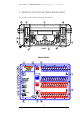

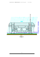
Table Of Contents

FIREMASTER IV "
MillenniumThree
" radio shooting system User’s manual
pins A of the RX-48 units and pin B to ALL corresponding pins B of the
RX-48 units. Only the LAST RX48 unit must be LOADED with a
terminating 120ohm resistor placed between A and B.
8. LINE 110/240Va.c. two-pole mains receptacle. It accepts standard 2-pole
cables to be plugged directly into the mains receptacle for battery charging.
The internal supply accepts automatically voltages from 110V up to 240V
a.c. 50 or 60Hz without need for range switching.
NOTE: Since the RX-48 Unit IS NOT PROVIDED with a LINE
SWITCH, the Unit itself, during the charging process, must be suitably
placed in order to allow the easy removal of the LINE CORD at any
moment, in case of emergency.
9. z Line LED (blue). This LED indicator turns ON whenever the Unit is
connected to a suitable MAINS receptacle for battery charging. The
charging process takes place automatically when the MAINS is connected
and the lever switch is in the OFF/EXT/CHARGE position.
10. Main power switch with 2 positions and rubber lever protection
(waterproof).
• ON Position: Unit switched ON and ACTIVE. The INTERNAL
batteries cannot be re-charged while operating.
• OFF/EXT/CHARGE Position: Unit switched OFF. In this position
the internal batteries can be RECHARGED simply connecting the line
cord to the mains receptacle. In emergency (failure of one or more of the
INTERNAL batteries) the EXTERNAL BATTERY PACK can be
connected to DIN connector placed on the CASE front.
11. OPTIONAL CONNECTOR for the EXTERNAL Battery Pack. 7-pole
DIN connector male. Normally this connector IS NOT MOUNTED on
the front-panel of the RX48 units: it is placed outside on the CASE front
(see case diagram, point 4).
12. z CHARGE LED (red). This indicator LED turns ON after all the
internal batteries have been successfully tested and the charging process
is running.
13. z TEST OK/FAULT LED (yellow). This indicator LED blinks during
the initial test of the internal batteries before the charging process takes
place. The TEST LED is turned OFF if the TEST is passed for all the
batteries and the charge starts normally. This LED is turned ON
(STEADY, with the “FAULT” meaning) if otherwise one or more
battery doesn’t pass the initial test.
14. zz BATTERY 3 – FIRE (red/green). This bi-color indicator LED
blinks GREEN during the normal charging process and turns ON RED
(steady) if the relative battery doesn’t pass the initial test or the charging
process is terminated with a FAULT condition.
15. zz BATTERY 2 – FIRE (red/green). This bi-color indicator LED
blinks GREEN during the normal charging process and turns ON RED
62