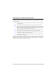
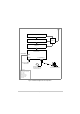
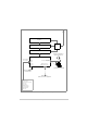
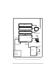
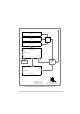
Configuring the Transmitter for Operational Use The transmitter can be configured for use in several different ways. Typical configurations are illustrated in the following figures: Fig 19 Local operation. Operating the transmitter using a microphone connected to the drive assembly front panel. Fig 20 Remote operation. Operating the transmitter from a voice switch or remote controller. Fig 21 With the transmitter connected through an RSE2 equipment.
Amplifier 1 Amplifier 2 Combiner Amplifier 3 Drive Assembly Optional facilities (use as required) Facilities Connector Reference Connector Microphone/Diagnostics Connector Frequency Counter for Maintenance Microphone/Headset for transmissions and monitoring sidetone Laptop (or PC) required when using VFP 28 Vdc output PTT relay output Antenna change-over output Tape output Ready output VSWR input signal BIT test input signal Inhibit input signal E-BIT input Fig 19 Transmitter Configured for Local
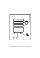
Amplifier 1 Amplifier 2 Combiner Amplifier 3 Microphone/Headset for engineering purposes Drive Assembly Optional facilities (use as required) Facilities Connector Reference Connector Microphone/Diagnostics Connector MARC Connector or MARC Audio Connector Laptop (or PC) required when using VFP Frequency Counter for Maintenance Audio and PTT Signals from Control Equipment 28 Vdc output PTT relay output Antenna change-over output Tape output Ready output VSWR input signal BIT test input signal Inhibi
Amplifier 1 Amplifier 2 Combiner Amplifier 3 Microphone/Headset for engineering purposes Drive Assembly Optional facilities (use as required) Facilities Connector Reference Connector Microphone/Diagnostics Connector MARC Connector Laptop (or PC) required when using VFP Frequency Counter for Maintenance Audio PTT MARC Data RSE2 Equipment Connectors 28 Vdc output PTT relay output Antenna change-over output Tape output Ready output VSWR input signal BIT test input signal Inhibit input signal E-BIT
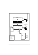
Amplifier 1 Amplifier 2 Combiner Amplifier 3 Microphone/Headset for engineering purposes Drive Assembly Optional facilities (use as required) Facilities Connector Reference Connector Microphone/Diagnostics Connector T1/E1 Connector Laptop (or PC) required when using VFP Frequency Counter for Maintenance E1 Data Stream containing Audio, Signalling and MARC Data E1-RIC E1 Data Stream containing Audio, Signalling and MARC Data Or (see Note) Radio Connectors 28 Vdc output PTT relay output Antenna c
Amplifier 1 Amplifier 2 Combiner Amplifier 3 Drive Assembly Reference Connector Microphone/Diagnostics Connector HDLC Connector T1/E1 Connector Facilities Connector Mode 2 Network Computer Fast Antenna Change-Over Switch T1/E1 Connector Reference Connector Antenna Connector Microphone/Diagnostics Connector T6R Receiver Frequency Counter for Maintenance connects to Reference Connector Laptop (or PC) required when using VFP.
Amplifier 1 Amplifier 2 Combiner Amplifier 3 Drive Assembly Reference Connector T1/E1 Connector Microphone/Diagnostics Connector Frequency Counter for Maintenance Laptop (or PC) required when using VFP Mode 3 Network Computer Fig 24 Transmitter Configured for Mode 3 Operation T6T 300 Watt VHF Transmitter Page 85 Installation
Front Panel Connectors Microphone/Diagnostics Connector The Microphone/Diagnostics connector is a self-locking 7-way DIN socket used for connecting a microphone, microphone/headset or PC. The connector pin-out is detailed in Table 16. Pin-out of the Microphone/Diagnostics connector looking into the mating face of the chassis mounted socket. A suitable free plug is detailed in Table 14 on page 70.
Rear Panel Connectors Fig 25 Drive Assembly External Signal Connectors Table 17 Rear Panel Connector Usage Connector Type Usage External speaker 3.5 mm stereo jack Connects an external loudspeaker for monitoring sidetone. MARC 9-way D-type Used to connect to a MARC remote site equipment RSE2 Used to connect a T6 controller or hub Used to terminate external audio and PTT signals when a remote site equipment or T6 controller is not used.
MARC Connector The MARC connector is a 9-way D-type socket used to connect the transmitter to a MARC remote site equipment, or it can also be used for normal remote operation. As an alternative to using this connector, the RJ48 style MARC Audio and MARC Data connectors can be used to provide the same functions. The MARC connector pin-out is shown below and detailed in Table 18. 5 Pin-out of MARC connector looking into the mating face of the chassis mounted socket.
MARC Audio Connector The MARC Audio connector is an 8-way RJ48 socket. It can be used as an alternative to the MARC connector for audio and PTT connections. The connector pin-out is shown below and detailed in Table 19. Numbering is shown looking from the top of the connector. The top is being viewed when the lever is on the bottom. RJ48 Plug Pin 1 Table 19 MARC Audio Connector Pin Number Signal Characteristic 1 Audio line in (-) Balanced 600 ohm, -30 to +10 dBm.
MARC or MARC Audio Connector T6T Transmitter MARC Audio Connector Audio is pins 1 and 2. PTT is pin 6 Ground is pin 7. Control Equipment Cross-Site Lines MARC Connector Audio is pins 2 and 3. PTT is pin 4 Ground is pin 1. Audio line 1 Audio Circuit Audio line 2 Reference Voltage (0 V, +14 V or -14 V) Set from front panel PTT PTT input requires at least 1 mA to operate. Input will draw no more than 6 mA.
MARC Data Connector The MARC Data connector is an 8-way RJ48 socket. It can be used as an alternative to the MARC connector for data connections. The connector pin-out is shown below and detailed in Table 20. Numbering is shown looking from the top of the connector. The top is being viewed when the lever is on the bottom.
T1/E1 Connector The T1/E1 8-way RJ48 socket is used to: ❑ Connect voice, signalling and RCMS data to a digital network ❑ Connect a Mode 3 network computer ❑ Connect a transmitter and receiver together when the receiver is configured as part of a Mode 2 base station. The connector pin-out is shown belown and detailed in Table 21. Numbering is shown looking from the top of the connector. The top is being viewed when the lever is on the bottom.
HDLC Connector The HDLC connector is an 8-way RJ48 socket used for connecting to a Mode 2 network computer. The connector pin-out is shown below and detailed in Table 22. Numbering is shown looking from the top of the connector. The top is being viewed when the lever is on the bottom. RJ48 Plug Pin 1 . Table 22 HDLC Connector Pin Signal Characteristic 1 HDLC RX A (input) 2 HDLC RX B (input) 3 HDLC CL A (output) 4 HDLC TX B (output) 5 HDLC TX A (output) 6 HDLC CL B (output) Pair to pin 3.
External Speaker The External Speaker connector is a 3.5 mm stereo jack used for connecting an external speaker to the transmitter to provide sidetone. This speaker should be a high impedance active type. Table 23 External Speaker Pin Signal Characteristic Tip Speaker drive (output) 0 to 3 V pk-pk. Connected directly to Ring. Ring Speaker drive (output) 0 to 3 V pk-pk. Connected directly to Tip. Sleeve Ground 0 V.
Facilities Connector The Facilities connector is a 15-way D-type filtered socket used for connecting to associated parts of a system. The connector pin-out is shown below and detailed in Table 24. 8 Pin-out of Facilities connector looking into the mating face of the chassis mounted socket. 1 15 A suitable free plug is detailed in Table 14 on page 70. 9 Table 24 Facilities Connector Pin Number Signal Characteristic 1 Ground 0 V.
T6T Transmitter (Main) Antenna Facilities Connector Antenna 28 Vdc (nominal) T6T Transmitter (Standby) Main/Standby Transmit Relay Facilities Connector 9 Control 5 Solid State Relay 6 8 Link Antenna Example This example shows the Antenna Change-over Output configured to control the antenna switching between main and standby transmitters. The potential on Facilities connector pin 6 is switched through to pin 5 when the standby transmitter is keyed; in this example, pin 6 is linked to ground.
Maintenance
Introduction This topic gives the scheduled and unscheduled maintenance procedures for the T6T 300 watt VHF transmitter and shows how to use the Virtual Front Panel (VFP). Scheduled Maintenance A scheduled maintenance procedure is given on page 100. Park Air recommends that this task be completed every twelve months. Unscheduled Maintenance Normally, the T6T transmitter is considered a Line Replaceable Unit (LRU) and should be replaced with a serviceable spare if a fault occurs.
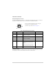
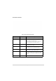
Software Configuration A white label fitted to the top cover lists the radio’s software configuration. In this example there are three fills: AM-Voice, Mode 2 and Mode 3. Software Configuration 2K1234 Part Order No. B63300HS Software Mode Part No.
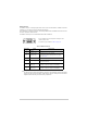
Scheduled Maintenance Park Air recommends that scheduled maintenance is carried out at twelve-monthly intervals. Scheduled maintenance comprises the following checks: Number Check Tools/Test Equipment Required 1 Ensure the equipment is clean and that external connectors are securely fitted. Camel hair brush/clean lint-free cloths. 2 Check and reset (if required) the transmitter’s internal frequency reference. VHF frequency counter. 3 Perform a BIT interruptive test.
Setting a 5-Offset Carrier Frequency If a 5-offset carrier frequency is required, set the offset using the following procedure: (1) Connect a 50 ohm frequency counter, through a 60 dB attenuator, to the combiner’s Antenna connector. (2) Set the required 25 kHz channel frequency; for example, 124.500 MHz. (3) From the AM-Voice Mode Settings Screen set the required offset (+4 kHz, -4 kHz, +8 kHz or -8 kHz); for example, a +4 kHz offset to give an operating frequency of 124.504 MHz.
To Initiate a BIT Test An interruptive BIT test cannot be initiated in Mode 2 or Mode 3. During an interruptive BIT test, the transmitter radiates modulated carrier waves at the set power. Users should therefore obtain the necessary authority before initiating a test. If the test is to be carried out with the antenna disconnected, ensure a load is fitted to the transmitter’s Antenna connector.
AC and DC Change-over Check If both ac and dc input supplies are connected to the transmitter, carry out the following check: (1) Confirm that both ac and dc supplies are connected to the transmitter. Ensure that the rear panel Supply switches are set to the I (on) position. (2) Confirm that the front panel Ready indicators are lit, the LCD is illuminated, and the transmitter is operational. (3) Switch off the ac supply from its source.
Unscheduled Maintenance WARNING Dangerous Voltage The instructions given in this topic involve connecting dangerous voltage to the transmitter. Maintenance should be carried out only by suitably qualified personnel. When an ac supply is connected, dangerous voltage is present within the transmitter. Care must be taken by personnel to avoid accidental contact with exposed circuitry during maintenance or alignment procedures.
Introduction This topic provides the user with detailed instructions on the removal and replacement of modules within the drive assembly and amplifiers. A faulty combiner must be replaced. When removing or refitting modules, observe antistatic handling precautions. Do not change any potentiometer (or link) settings unless detailed in these instructions. Potentiometers have been set using specialist equipment.
T6T VHF Amplifier Procedures Top and Bottom Covers One of the top cover screws is covered with a warranty label that should not be tampered with unless Park Air Customer Support has advised otherwise. When authorisation has been made the following procedures should be followed. To remove the top cover, locate and unscrew the 19 countersunk screws securing the top cover to the mainframe. Access can then be gained to the Interface module and PSU Regulation module.
Refitting To refit the Interface module, proceed as follows: (1) Place the module in position. Ensure no wires are trapped by the module. (2) Ensure the module interface connectors CN5 and CN8 are located correctly and are aligned with the screw holes in the rear panel. Fit the four screwloc 8 mm-4-40 UNC screws and wavy washers, previously removed, but leave them loose. (3) Fit the two M3 x 8 mm screws, previously removed, that secure the blanking plate and Interface module, but leave them loose.
Removing and Refitting the PSU Regulation Module The PSU Regulation module is located as shown in Fig 34. A module removal diagram is shown in Fig 38. WARNING Dangerous Voltage Dangerous voltage is present within the T6T VHF amplifier. Care must be taken by personnel to avoid accidental contact with exposed circuitry when the covers are removed and power is applied to the radio.
(5) Re-establish the ac and/or dc supplies. (6) Switch power on at the radio using the rear mounted Supply switch. (7) Ensure the front panel Ready indicator is lit and the Alarm indicator is unlit. (8) Carry out a BIT interruptive test as detailed in the procedure To Initiate a BIT Test on page 102. (9) Set the rear panel Supply switch to Standby. Isolate the amplifier from the ac and/or dc supplies. (10) Refit the amplifier top cover. The amplifier can now be returned to service.
(3) Connect the dc wires to the eight connector terminal block, red to terminal 1 and terminal 2 and black to terminal 5 and terminal 6. (4) Connect CN4. (5) Taking care not to damage the plastic supply guard, lower the power supply into position and secure from the bottom half of the unit using two countersunk screws, previously removed, for each power supply. (6) Connect the drive assembly cables at CN5 and CN8. Connect the antenna cable to the Combiner.
❑ CN14 6-way connector ❑ CN15 10-way connector ❑ CN16 SMB connector ❑ CN17 SMB connector ❑ CN18 SMB connector ❑ CN22 QMA connector ❑ CN23 QMA connector ❑ CN24 QMA connector ❑ CN25 SMB connector ❑ CN26 SMB connector ❑ CN27 SMB connector. (3) The Combiner BIT module is secured from both sides of the chassis thus requiring removal of the Power Supply modules. Refer to page 109 and remove both Power Supply modules.
Removing and Refitting the PA Modules Caution Repairs When carrying out repairs to the PA module, care must be taken not to damage the gasket. If the strips become damaged, they must be replaced. Failure to comply with this instruction may compromise the transmitter’s Electromagnetic Compatibility (EMC) and breach European Commission regulations. When screws are inserted into the PA casting care must be taken not to exceed a torque of 6 Ibs/inch when tightening.
(8) Remove the two screws holding the upper heatsink to the rear panel and the countersunk screw securing it to the front of the chassis. Slowly withdraw the upper PA module from the mainframe taking care not to snag the wiring looms. Note that SMB connector CN10 is located within the bottom of the heatsink fins and should be disconnected using long nosed pliers. Do not attempt to remove the connector by pulling on the cable.
Removing and Refitting the Front Panel PCB The Front Panel PCB is located as shown in Fig 42. Removing this assembly necessitates the removal of both Power Supply modules and partial removal of the Combiner BIT module. WARNING Dangerous Voltage Dangerous voltage is present within the T6T VHF amplifier. Care must be taken by personnel to avoid accidental contact with exposed circuitry when the covers are removed and power is applied to the radio.
(10) Set the rear panel Supply switch to Standby. Isolate the amplifier from the ac and/or dc supplies. (11) Refit the amplifier top and bottom covers. The amplifier can now be returned to service. Removing and Refitting the Cooling Fans The cooling fans are mounted at the rear of the PA modules as shown in Fig 34. The removal diagram is shown in Fig 43. Removal Before attempting to remove the fan, ensure that the T6T VHF amplifier is isolated from the ac and dc input supplies.
T6T VHF Drive Assembly Procedures Removing the Top Cover WARNING Dangerous Voltage Dangerous voltage is present within the T6T VHF drive assembly. Care must be taken by personnel to avoid accidental contact with exposed circuitry when the covers are removed and power is applied to the radio. To remove the top cover, ensure that the drive assembly is isolated from the ac and dc input supplies. Then locate and unscrew the 13 screws securing the top cover to the mainframe.
(5) Remove the module from the chassis. Refitting To refit the Processor module, proceed as follows: (1) Place the module in position. Ensure no wires are trapped by the module. Ensure jumper J2 on the module is set to ‘T’ for drive assembly (see Fig 30).
compatible operating and Fill software. Park Air keeps records of module software in all radios supplied. Care must be taken when using a module removed from another radio as this module may not have compatible software. (11) Download the saved radio settings from file using the VFP. Alternatively, the settings can be edited by hand as described in the Operation topic. Once entered, ensure the required settings appear in the VFP screen.
(5) Remove the module from the chassis.
Removing and Refitting the Drive Module The Drive module is located as shown in Fig 44. A module removal diagram is shown in Fig 48. WARNING Dangerous Voltage Dangerous voltage is present within the T6T VHF drive assembly. Care must be taken by personnel to avoid accidental contact with exposed circuitry when the covers are removed and power is applied to the radio. Removal Before attempting to remove the Drive module, ensure that the drive assembly is isolated from the ac and dc input supplies.
(7) Switch power on at the radio using the rear mounted Supply switch. (8) Ensure the front panel Ready indicator is lit and the Alarm indicator is unlit. (9) Carry out a BIT interruptive test as detailed in the procedure To Initiate a BIT Test on page 102. (10) Set the rear panel Supply switch to Standby. Isolate the drive assembly from the ac and/or dc supplies. (11) Refit the drive assembly top cover. The drive assembly can now be returned to service.
(3) Remove the eight M3 x 8 mm captive washer screws that secure the module to the drive assembly mainframe. (4) Remove the module from the chassis. Refitting To refit the PA Control module, proceed as follows: (1) Place the module in position. Ensure no wires are trapped by the module. (2) Fit the eight M3 x 8 mm captive washer screws, previously removed, that secure the module to the drive assembly mainframe.
Removing and Refitting the Power Supply The Power Supply is located as shown in Fig 44. A module removal diagram is shown in Fig 50. WARNING Dangerous Voltage Dangerous voltage is present within the drive assembly. Care must be taken by personnel to avoid accidental contact with exposed circuitry when the covers are removed and power is applied to the radio. Removal Before attempting to remove the Power Supply, ensure that the drive assembly is isolated from the ac and dc input supplies.
(11) Switch power to Standby using the rear mounted Supply switch. Isolate the drive assembly from the ac and/or dc supplies. (12) Refit the drive assembly top and bottom covers. The drive assembly can now be returned to service. Removing and Refitting the Front Panel PCB The Front Panel assembly is located as shown in Fig 44. An assembly and PCB removal diagram is shown in Fig 51. WARNING Dangerous Voltage Dangerous voltage is present within the T6T VHF drive assembly.
(5) Route the SMB connector to CN5 on the PA Control module and connect it. (6) Re-connect the six Amplifier Out connectors, CN1 to CN6. (7) Re-establish the ac and/or dc supplies. (8) Switch power on at the radio using the rear mounted Power switch. (9) Ensure the front panel Ready indicator is lit and the Alarm indicator is unlit. (10) Carry out a BIT interruptive test as detailed in the procedure To Initiate a BIT Test on page 102.
Virtual Front Panel (VFP) Virtual Front Panel (VFP) software is supplied on CD and is compatible with any PC or laptop running Windows 2000™ or Windows XP™. The VFP allows changes to a radio’s settings and channel information, it displays the current BIT state, displays BIT history, allows security locks to be set, and provides maintenance facilities. A radio can be set up using the front panel Scroll/Select switch and LCD, or by using the VFP.
Installing the VFP Software The VFP software is supplied by Park Air on CD. The software can be run from the Main page or installed on your PC via Explorer. To install the software onto your PC: (1) Using explorer, display the contents of the CD supplied by Park Air. Identify the file named S0473Vxx.EXE (where xx is the version number). (2) Using the mouse, right click on the file and then select Copy. (3) Display the Windows desktop. Right click anywhere on the desktop and select Paste.
Settings Window This window lists all attributes that can be adjusted by the user. If any individual attribute is clicked on using the mouse, help information is displayed in the Status Information window showing the range of adjustment for that attribute. Click on the value and use the keyboard to amend it; press Enter to confirm the new value noting that the amended text is green until it is downloaded into the radio. Any invalid parameters are not indicated until the Settings are downloaded to the radio.
To Change the Drive Assembly Profile or Save a Profile (1) Using a PC to Radio Interconnection Lead, Park Air part number 17E12600001, connect the drive assembly’s front panel Microphone/Diagnostics connector to the PC’s Com Port 1 or Com Port 2 (note which Com Port is used). (2) Run up the VFP software and check that a blank VFP screen (see Fig 32) is displayed. Fig 32 Blank VFP Screen (3) At the Menu Bar, click on Serial Port and select either Com 1 or Com 2.
(6) Download the radio’s profile as shown on the VFP screen to either the radio, or to a file. To download into the radio, select Radio > Send > All or, Radio > Send > Settings or, Radio > Send > Channel To download to a file, select File > Send > All or, File > Send > Settings or, File > Send > Channel or, File > Send > BIT (7) Check that after downloading to a radio, no invalid parameters are returned (such parameters are displayed as red text).
(5) At the Menu Bar, click on Serial Port and select either Com 1 or Com 2. The selection must correspond to the port used to connect to the radio. (6) At the Menu Bar select Radio > Retrieve > All. (7) At the Menu Bar select Radio > Calibrate. The Confirm screen will then be displayed to remind you that a dummy load must be connected before proceeding. (8) With the Confirm screen displayed and dummy load connected, select Yes to continue with the calibrate routine.
Intentionally Blank
Power Supply Modules PSU Regulation Module Interface Module Top View Fig 34 T6T VHF Amplifier Module Location Diagram Front Panel Assembly PA Modules Bottom View Combiner BIT Module
8 9 10 11 12 13 14 CN5-8 CN5-9 CN5-10 CN5-11 CN5-12 CN5-13 CN5-14 CN5-15 0V=off,opencollector=on Remote on/off CN2-9 CN2-10 CN15-9 CN15-10 Fan Fan 10 CN6 PA-2 Connections PA Heatsink PA-1 CN24-1 PA Ground Fan Control Name RF Output 9 Antenna Port Name CN3-1 CN16-1 Connections RF Drive Interface Name Forward Power Sense Name PA-2 Fail Indication Ground Combiner BIT module 8 CN4-1 CN27-1 Connections Interface Combiner BIT module 7 CN2-8 CN15-8 Connecti
PA-1 13 Connections Connections CN18-1 Connections CN23-1 CN10-3 TTL - High for bias on 0V 0V PSU off Name CN6-5 CN6-6 17 CN12-5 CN12-6 Ground DC Derived Supply Ground Pin Diode - ve CN1-3 & 4 CN2-1 CN2-2 CN3-3 CN3-2 CN3-1 n/c CN7-2 CN7-3 CN7-4 CN7-5 CN7-6 CN7-7 CN7-8 n/c V Unregulated Ground AC Derived Supply CN1-1 & 2 CN7-1 Combiner BIT module Regulation 0 V=on PSU off CN6-4 CN12-4 Connections o/c ok PSU ok CN6-3 Connections CN11-3 CN11-2 CN3-4 Connections CN3-6
CN4 CN7 CN6 Fig 37 T6T VHF Amplifier Interface Module - Removal and Refitting Detail CN3 CN2
CN7 CN2 CN3 CN4 CN1 Fig 38 T6T VHF Amplifier PSU Regulation Module - Removal and Refitting Detail CN6
PSU to Bit Combiner (dc Connections) Bit Combiner to PSU (fan control) PSU-1 Fig 39 T6T VHF Amplifier Power Supplies - Removal and Refitting Detail PSU-2 PSU to Bit Combiner (dc Connections) Bit Combiner to PSU (fan control)
CN4 CN14 CN13 CN15 CN26 CN23 CN22 CN27 CN25 CN24 Connector Locations CN17 CN16 Fig 40 T6T VHF Amplifier Combiner BIT Module - Removal and Refitting Detail CN7 CN12 CN5 CN6 CN11CN10 CN1 CN3 CN2 CN18
Fig 41 T6T VHF Amplifier PA Modules - Removal and Refitting Detail PA-2 PA-1
Fig 42 T6T VHF Amplifier Front Panel PCB - Removal and Refitting Detail To Interface module CN7
power connectionshere here Power connections Finger guard Finger guard AIRFLOW Fig 43 T6T VHF Amplifier Cooling Fans - Removal and Refitting Detail
Power Supply PSU Regulation Module Processor Module Top View Front Panel Assembly PA Control Module Fig 44 T6T VHF Drive Assembly Module Location Diagram Drive Module AMPLIFIER OUT ANTENNA DANGER HIGH RF VOLTAGES CONNECT ANTENNA BEFORE USE T1/E1 HDLC MARC AUDIO FUSE F1 DC SUPPLY DISCONNECT SUPPLIES WHEN NOT IN USE 21.
LCD RS CN1-5 CN4-5 CN2-2 CN2-3 +5 V Supply CN1-16 CN1-17 CN1-18 CN4-16 CN4-17 CN4-18 Ground LED RX (not used) Turn + CN1-21 CN1-22 CN1-23 CN1-24 CN1-25 CN1-26 CN1-27 CN1-28 CN1-29 CN4-21 CN4-22 CN4-23 CN4-24 CN4-25 CN4-26 CN4-27 CN4-29 CN1-32 CN1-33 CN1-34 CN4-32 CN4-33 CN4-34 5 V pull-up 0 V=PTT, 5 V pull-up=PTT 0V Mic PTT Ground 0V Ground +15 V +15 V Supply +5 V Supply +5 V Supply CN3-3 CN3-4 CN4-3 CN4-4 -15 V Supply ac Detect dc Detect V Unreg V Unre
CN5 CN1 CN12 CN4 Fig 46 T6T VHF Drive Assembly Processor Module - Removal and Refitting Detail CN6 CN3
CN9 CN8 CN5 CN4 CN2 CN7 CN6 Fig 47 T6T VHF Drive Assembly PSU Regulation Module - Removal and Refitting Detail CN8 Brown (L) Blue (N)
CN9 CN7 CN8 CN11 Driver Module Fig 48 T6T VHF Drive Assembly Drive Module - Removal and Refitting Detail CN10
CN1 CN5 CN2 3 PC CN4 CN4 CN3 CN3 Fig 49 T6T VHF Drive Assembly PA Control Module - Removal and Refitting Detail CN6
Power Supply Power Supply To PSU Regulation Module Fig 50 T6T VHF Drive Assembly Power Supply - Removal and Refitting Detail CN1 CN6 CN9
Diagram A Diagram B Front panel Fig 51 T6T VHF Drive Assembly Front Panel PCB - Removal and Refitting Detail head grub screw Allen headAllen grub screw 1 To PA Control module CN5 Front panel PCB Front panel PCB To Processor module CN4