
User's Manual Part 2
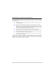
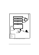
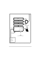
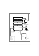
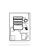
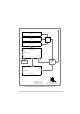
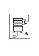
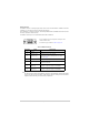
Table Of Contents
- Maintenance
- Introduction
- Scheduled Maintenance
- Unscheduled Maintenance
- Introduction
- Tools, Materials and Test Equipment Required
- T6T VHF Amplifier Procedures
- Top and Bottom Covers
- Removing and Refitting the Interface Module
- Removing and Refitting the PSU Regulation Module
- Removing and Refitting the Power Supply Modules
- Removing and Refitting the Combiner BIT Module
- Removing and Refitting the PA Modules
- Removing and Refitting the Front Panel PCB
- Removing and Refitting the Cooling Fans
- T6T VHF Drive Assembly Procedures
- Removing the Top Cover
- Removing and Refitting the Processor Module
- Removing and Refitting the PSU Regulation Module
- Removing and Refitting the Drive Module
- Removing the Bottom Cover
- Removing and Refitting the PA Control Module
- Removing and Refitting the Power Supply
- Removing and Refitting the Front Panel PCB
- Virtual Front Panel (VFP)

T6T 300 Watt VHF Transmitter Page 83 Installation
Fig 22 Transmitter Configured for use with an E1-RIC
Note:
E1-RIC can be used in an E1 digital end-to-end system, or using 4-wire E and M lines.
Amplifier 1
Amplifier 2
Amplifier 3
Combiner
Drive Assembly
Reference
Connector
Microphone/Diagnostics
Connector
Microphone/Headset for
engineering purposes
Laptop (or PC)
required when using VFP
Frequency Counter
for Maintenance
Facilities
Connector
Antenna change-over output
Ready output
Tape output
BIT test input signal
Inhibit input signal
28 Vdc output
VSWR input signal
PTT relay output
E-BIT input
Optional facilities
(use as required)
T1/E1 Connector
E1-RIC
Radio
Connectors
E1 Data Stream
containing Audio,
Signalling and
Audio and PTT
from
control equipment
MARC Data
to and from
control centre
MARC Data
E1 Data Stream
containing Audio,
Signalling and
MARC Data
Or (see Note)