
User's Manual Part 2
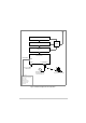
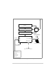
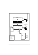
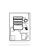
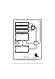
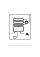
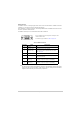
Table Of Contents
- Maintenance
- Introduction
- Scheduled Maintenance
- Unscheduled Maintenance
- Introduction
- Tools, Materials and Test Equipment Required
- T6T VHF Amplifier Procedures
- Top and Bottom Covers
- Removing and Refitting the Interface Module
- Removing and Refitting the PSU Regulation Module
- Removing and Refitting the Power Supply Modules
- Removing and Refitting the Combiner BIT Module
- Removing and Refitting the PA Modules
- Removing and Refitting the Front Panel PCB
- Removing and Refitting the Cooling Fans
- T6T VHF Drive Assembly Procedures
- Removing the Top Cover
- Removing and Refitting the Processor Module
- Removing and Refitting the PSU Regulation Module
- Removing and Refitting the Drive Module
- Removing the Bottom Cover
- Removing and Refitting the PA Control Module
- Removing and Refitting the Power Supply
- Removing and Refitting the Front Panel PCB
- Virtual Front Panel (VFP)

T6T 300 Watt VHF Transmitter Page 85 Installation
Fig 24 Transmitter Configured for Mode 3 Operation
Amplifier 1
Amplifier 2
Amplifier 3
Combiner
Drive Assembly
Reference
Connector
Microphone/Diagnostics
Connector
Laptop (or PC)
required when using VFP
Frequency Counter
for Maintenance
T1/E1 Connector
Mode 3
Network
Computer