
User's Manual Part 2
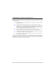
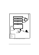
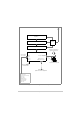
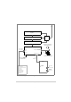
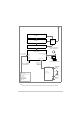
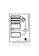
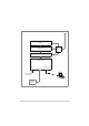
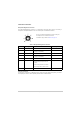
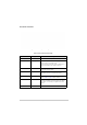
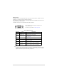
Table Of Contents
- Maintenance
- Introduction
- Scheduled Maintenance
- Unscheduled Maintenance
- Introduction
- Tools, Materials and Test Equipment Required
- T6T VHF Amplifier Procedures
- Top and Bottom Covers
- Removing and Refitting the Interface Module
- Removing and Refitting the PSU Regulation Module
- Removing and Refitting the Power Supply Modules
- Removing and Refitting the Combiner BIT Module
- Removing and Refitting the PA Modules
- Removing and Refitting the Front Panel PCB
- Removing and Refitting the Cooling Fans
- T6T VHF Drive Assembly Procedures
- Removing the Top Cover
- Removing and Refitting the Processor Module
- Removing and Refitting the PSU Regulation Module
- Removing and Refitting the Drive Module
- Removing the Bottom Cover
- Removing and Refitting the PA Control Module
- Removing and Refitting the Power Supply
- Removing and Refitting the Front Panel PCB
- Virtual Front Panel (VFP)

T6T 300 Watt VHF Transmitter Page 86 Installation
Front Panel Connectors
Microphone/Diagnostics Connector
The Microphone/Diagnostics connector is a self-locking 7-way DIN socket used for connecting a
microphone, microphone/headset or PC. The connector pin-out is detailed in Table 16.
Reference Connector
The Reference connector is an SMB plug used to monitor the radio’s reference frequency. It monitors
the frequency at a level of 100 mV (±50 mV) with less than -10 dBc harmonics.
Table 16 Microphone/Diagnostics Connector
Pin Number Signal Characteristic Usage
1 Microphone ground 0 V. Microphone/Headset
2 Transmit data RS232. 115200 baud, 8 data bits, 1 stop bit,
no parity, no handshaking.
PC
3 Microphone PTT 0 V to PTT. Microphone/Headset
4 Receive data RS232. 115200 baud, 8 data bits, 1 stop bit,
no parity, no handshaking.
PC
5 Sidetone – Microphone/Headset
6 Microphone input To ensure correct VOGAD operation, the
following microphone input levels are
required:
Passive setting: between 2 and 35 mV
Active setting: between 8 and 140 mV.
Microphone/Headset
7 Ground 0 V. PC
Pin-out of the Microphone/Diagnostics connector looking into
the mating face of the chassis mounted socket.
A suitable free plug is detailed in Table 14 on page 70.