
User's Manual

M7X and M7R Page 5-30 Maintenance
Back to Menu
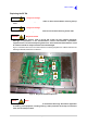
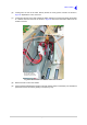
(6) Looking from the rear of the radio, identify the RF PA 3-way power connector as shown in
Fig 5-20. Separate the in-line connector.
(7) Looking from the rear of the radio, identify the ribbon cable that connects from the RF PA module
to a chassis mounted connector as shown in Fig 5-20. Disconnect the ribbon cable from the
chassis connector.
Fig 5-20 RF PA Power and Ribbon Cable Connections
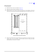
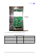
(8) Remove the RF PA from the chassis.
(9) A thermal pad is fitted between the RF PA and the chassis (which is a heatsink). The old thermal
pad should now be removed by peeling it off (see Fig 5-21).
RF PA In-Line
Power Connector
RF PA Ribbon Cable
Connector
This photograph taken
from the rear of the radio
with the RF PA on the left.
RF PA
Module