
Brochure


Parker Hannifin Corporation, Climate and Industrial Controls Group, Cleveland, OH
Page 22 / Catalog E-1, Thermostatic & Automatic Expansion Valves
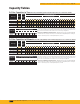
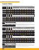
R-404A Capacities in Tons (R-507 Refrigerant & Liquid Temperature Correction Factor below)
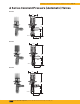
Valve Type Orifice
Nominal
Capacity
(Tons)
Capacity
Range
(Tons)
Evaporator Temperature °F
40°F 20°F 0°F
Pressure Drop (PSI)
75 100 125 150 175 200 75 100 125 150 175 200 75 100 125 150 175 200
A1, A2, AT B 2 1 to 2 1.73 2.00 2.24 2.45 2.65 2.83 1.66 1.92 2.15 2.35 2.54 2.72 1.51 1.74 1.95 2.13 2.30 2.46
A4 — 1/2 1/4 to 3/4 0.65 0.75 0.84 0.92 0.99 1.06 0.62 0.72 0.80 0.88 0.95 1.02 0.57 0.65 0.73 0.80 0.86 0.92
A7-AA AA 1/2 1/8 to 1/2 0.43 0.50 0.56 0.61 0.66 0.71 0.42 0.48 0.54 0.59 0.63 0.68 0.38 0.44 0.49 0.53 0.58 0.62
A7-A A 1 1/4 to 1 0.87 1.00 1.12 1.22 1.32 1.41 0.83 0.96 1.07 1.18 1.27 1.36 0.75 0.87 0.97 1.07 1.15 1.23
A7-B B 2 1 to 2 1.73 2.00 2.24 2.45 2.65 2.83 1.66 1.92 2.15 2.35 2.54
2.72 1.51 1.74 1.95 2.13 2.30 2.46
A7-C C 4 1-1/2 to 4 3.46 4.00 4.47 4.90 5.29 5.66 3.33 3.84 4.29 4.70 5.08 5.43 3.01 3.48 3.89 4.26 4.60 4.92
AS, ASB20 — 1 1/4 to 1 0.87 1.00 1.12 1.22 1.32 1.41 0.83 0.96 1.07 1.18 1.27 1.36 0.75 0.87 0.97 1.07 1.15 1.23
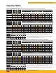
Valve Type Orifice
Nominal
Capacity
(Tons)
Capacity
Range
(Tons)
Evaporator Temperature °F
-10°F -20°F -40°F
Pressure Drop (PSI)
100 125 150 175 200 225 125 150 175 200 225 250 125 150 175 200 225 250
A1, A2, AT B 2 1 to 2 1.48 1.65 1.81 1.96 2.09 2.22 1.36 1.49 1.61 1.73 1.83 1.93 0.87 0.96 1.03 1.10 1.17 1.23
A4 — 1/2 1/4 to 3/4 0.56 0.62 0.68 0.73 0.78 0.83 0.51 0.56 0.61 0.65 0.69 0.72 0.33 0.36 0.39 0.41 0.44 0.46
A7-AA AA 1/2 1/8 to 1/2 0.37 0.41 0.45 0.49 0.52 0.56 0.34 0.37 0.40 0.43 0.46 0.48 0.22 0.24 0.26 0.28 0.29 0.31
A7-A A 1 1/4 to 1 0.74 0.83 0.91 0.98 1.05 1.11 0.68 0.75 0.81 0.86 0.92 0.96 0.44 0.48 0.52 0.55 0.59 0.62
A7-B B 2 1 to 2 1.48 1.65 1.81 1.96 2.09 2.22 1.36 1.49 1.61 1.73 1.83
1.93 0.87 0.96 1.03 1.10 1.17 1.23
A7-C C 4 1-1/2 to 4 2.96 3.31 3.63 3.92 4.19 4.44 2.73 2.99 3.23 3.45 3.66 3.86 1.74 1.91 2.06 2.21 2.34 2.47
AS, ASB20 — 1 1/4 to 1 0.74 0.83 0.91 0.98 1.05 1.11 0.68 0.75 0.81 0.86 0.92 0.96 0.44 0.48 0.52 0.55 0.59 0.62
Capacity Tables
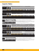
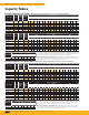
R-404A Capacities in Kilowatts (R-507 Refrigerant & Liquid Temperature Correction Factor below)
nGold areas are standard conditions.
Valve Type Orifice
Nominal
Capacity
(kW)
Capacity
Range
(kW)
Evaporator Temperature °C
10°C 0°C -10°C
Pressure Drop (BAR)
5 7 9 10 12 14 5 7 9 10 12 14 5 7 9 10 12 14
A1, A2, AT B 7 4 to 7 6.06 7.17 8.14 8.58 9.39 10.1 5.88 6.96 7.89 8.32 9.11 9.84 5.58 6.60 7.48 7.89 8.64 9.33
A4 — 3 1 to 3 2.27 2.69 3.05 3.22 3.52 3.80 2.21 2.61 2.96 3.12 3.42 3.69 2.09 2.48 2.81 2.96 3.24 3.50
A7-AA AA 2 1/2 to 2 1.52 1.79 2.03 2.14 2.35 2.54 1.47 1.74 1.97 2.08 2.28 2.46 1.39 1.65 1.87 1.97 2.16 2.33
A7-A A 4 1 to 4 3.03 3.59 4.07 4.29 4.70 5.07 2.94 3.48 3.95 4.16 4.56 4.92 2.79 3.30 3.74 3.94 4.32 4.67
A7-B B 7 4 to 7 6.06 7.17 8.14 8.58 9.39 10.1 5.88 6.96 7.89 8.32 9.11
9.84 5.58 6.60 7.48 7.89 8.64 9.33
A7-C C 14 5 to 14 12.1 14.3 16.3 17.2 18.8 20.3 11.8 13.9 15.8 16.6 18.2 19.7 11.2 13.2 15.0 15.8 17.3 18.7
AS, ASB20 — 4 1 to 4 3.03 3.59 4.07 4.29 4.70 5.07 2.94 3.48 3.95 4.16 4.56 4.92 2.79 3.30 3.74 3.94 4.32 4.67
Valve Type Orifice
Nominal
Capacity
(kW)
Capacity
Range
(kW)
Evaporator Temperature °C
-20°C -30°C -40°C
Pressure Drop (BAR)
7 9 10 12 14 16 9 10 12 14 16 17 9 10 12 14 16 17
A1, A2, AT B 7 4 to 7 5.67 6.43 6.77 7.42 8.02 8.57 4.80 5.06 5.54 5.99 6.40 6.60 3.09 3.26 3.57 3.86 4.12 4.25
A4 — 3 1 to 3 2.13 2.41 2.54 2.78 3.01 3.21 1.80 1.90 2.08 2.24 2.40 2.47 1.16 1.22 1.34 1.45 1.55 1.59
A7-AA AA 2 1/2 to 2 1.42 1.61 1.69 1.86 2.00 2.14 1.20 1.26 1.39 1.50 1.60 1.65 0.77 0.81 0.89 0.96 1.03 1.06
A7-A A 4 1 to 4 2.83 3.21 3.39 3.71 4.01 4.28 2.40 2.53 2.77 2.99 3.20 3.30 1.55 1.63 1.78 1.93 2.06 2.12
A7-B B 7 4 to 7 5.67 6.43 6.77 7.42 8.02 8.57 4.80 5.06 5.54 5.99 6.40
6.60 3.09 3.26 3.57 3.86 4.12 4.25
A7-C C 14 5 to 14 11.3 12.9 13.5 14.8 16.0 17.1 9.60 10.1 11.1 12.0 12.8 13.2 6.18 6.52 7.14 7.71 8.24 8.50
AS, ASB20 — 4 1 to 4 2.83 3.21 3.39 3.71 4.01 4.28 2.40 2.53 2.77 2.99 3.20 3.30 1.55 1.63 1.78 1.93 2.06 2.12
nGold areas are standard conditions.
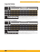
Refrigerant
Liquid Temperature Entering AEV
0°F 20°F 40°F 60°F 80°F 100°F 120°F 140°F
Correction Factor
R-404A 2.04 1.84 1.64 1.43 1.22 1.00 0.77 0.53
R-507 1.95 1.76 1.56 1.37 1.18 0.98 0.76 0.50
Refrigerant
Liquid Temperature Entering AEV
-10°C 0°C 10°C 20°C 30°C 40°C 50°C 60°C
Correction Factor
R-404A 1.98 1.79 1.60 1.41 1.21 1.00 0.79 0.56
R-507 1.89 1.71 1.53 1.35 1.17 0.98 0.78 0.53
These factors include corrections for liquid refrigerant density and net refrigerating effect, and are based
on an evaporator temperature of 0°F. However, they may be used for any evaporator temperature from
-40°F to 40°F since the variation in the actual factors across this range is insignificant.
AEV Capacity = AEV Rating x CF Liquid Temperature – Example: Actual capacity of an A7-B using R-507
at a 20°F evaporator, 175 psi pressure drop across the AEV, and a 80°F liquid temperature entering the
AEV = 2.54 (from rating chart) x 1.18 (CF liquid temperature) = 3.00 tons
These factors include corrections for liquid refrigerant density and net refrigerating effect, and are based
on an evaporator temperature of -15°C. However, they may be used for any evaporator temperature from
-40°C to 10°C since the variation in the actual factors across this range is insignificant.
AEV Capacity = AEV Rating x CF Liquid Temperature – Example: Actual capacity of an A7-B using R-507
at a 0°C evaporator, 12 bar pressure drop across the AEV, and a 30°C liquid temperature entering the
AEV = 9.11 (from rating chart) x 1.17 (CF liquid temperature) = 10.7 kW