Automation Linear actuators HLE with timing belt drive HLEZ with rack-and-pinion drive Catalogue: 192-510011N7 Version 7 / May 1999
HLE – Linear actuators with timing belt drive Automation 2 Parker Hannifin GmbH Electromechanical Division
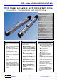
HLE – Linear actuators with timing belt drive HLE linear actuators with timing belt drive - for guiding, transporting and positioning Contents: The HLE - a proven technology.............. 4 Construction of the HLE.......................... 5 Technical data .......................................... 6 Dimensional drawings ............................. 8 HLE 80...................................................... 8 HLE100................................................... 10 HLE 150.........................
HLE – Linear actuators with timing belt drive The HLE - a proven technology The universal one Our experience The HLE linear actuator offers an appropriate solution for all motion tasks. It is ideal for use as a single axis, or as a component in a multiple axis system. It has been developed for rapid linear movements over long stroke distances. The HLE provides a simple machine and system element and can be used without the need for any specialised knowledge.
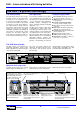
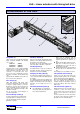
HLE – Linear actuators with timing belt drive Construction of the HLE 4 1 9 5 7 6 3 8 2 The timing belt has no play and is reinforced by integral steel wires, thereby ensuring maximum travel speeds and repeatability. When used in conjunction with the clamping profile (page 26) this allows for simple incorporation in a multi-axis system. i Simple and adjustable attachment of operating cams or switch lugs by means of longitudinal grooves on the sides and on the underside of the plate.
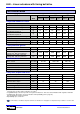
HLE – Linear actuators with timing belt drive Technical data HLE size 80 100 150 Unit Standard Steel strip cover Standard Steel strip cover Standard Steel strip cover HLE with standard carriage S kg 7.1 7.9 11.5 12.7 28.6 31.2 HLE with extended carriage E Weight of standard carriage + load attachment plate S Weight of extended carriage + load attachment plate E Weight per meter of additional length kg 8.4 9.9 14.6 15.8 35.9 38.5 kg 1.5 1.7 2.5 2.8 6.7 7.3 kg 2.5 2.8 4.
HLE – Linear actuators with timing belt drive Mz Fz Fx Mx Fy My Fx [N] (load-bearing capacity of timing belt) 3000 The forces and torques the carriage and the timing belt are capable of transferring are speed-dependent. The curves shown in the graphs apply to a standard carriage (S/T).
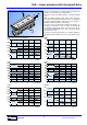
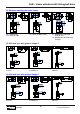
34+0,2 50 100 Automation 40+0,2 50 8 61 122 140 80 164 (209) 110H7 Pulley for drive shaft Ø25 Key complying with DIN 6885 T1, type A gearbox flange Q (35) stroke M5 70 120 100 7 125 Safety travel 4,5+0,3 12,5+0,2 Slots compatible with DIN508 T-nuts DIN787 T-bolts Detail X 80 40±0,3 70 8,1+0,3 X 50 12,5+0,2 4,5+0,3 8,1+0,3 100 Dimensions in () apply in combination with steel strip cover. Parts indicated in broken lines: Steel strip cover option.
HLE – Linear actuators with timing belt drive 100 40 87 SR SL 40 50 100 50 100 50 HLE80 drive housing with drive shafts 29 87 96 20h6 20h9 70 120 20h8 70 70 120 120 SL: shaft on left SR: shaft on right SB: shafts on both sides RL: gearbox on right and shaft on left LR: gearbox on left and shaft on right 100 50 100 50 100 50 HLE 80 dual axis with gearbox flange Q 80 A > 500 215 < A < 500 80 80 80 215 70 70 120 70 120 120 Centre distance A between 80215 mm Centre distanc
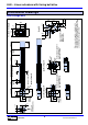
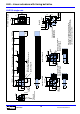
132 Automation 4xM8 Pitch circle Ø130 64,4 63,4±0,2 52 10 85 150 85 ±0,1 64,4 132 4,5+0,3 132 64,4 8,1+0,3 Detail X 100 60±0,3 90 Dimensions in () apply in combination with steel strip cover. Parts indicated in broken lines: Steel strip cover option. Casing projection at drive and tensioning station approx. 1mm.
HLE – Linear actuators with timing belt drive 40 87 40 87 SR 132 64,4 132 64,4 132 64,4 HLE100 drive housing with drive shafts 40 87 20h6 SL 20h9 85 150 20h8 85 150 85 150 SL: shaft on left SR: shaft on right SB: shaft on both sides RL: gearbox on right and shaft on left LR: gearbox on left and shaft on right 132 64,4 132 64,4 64,4 132 HLE 100 dual axis with gearbox flanges Q and R A > 500 100 225 85 150 85 150 Centre distance A between 100-225 mm Automation 100 85 150 100 100
104 102 Automation 4xM8 TK Ø130 187 Timing belt tensioning screws 54 115 198 110H7 234(279) (35) A A 350 standard carriage 500 extended carriage (35) Dimensions in () apply in combination with steel strip cover. Parts indicated in broken lines: Steel strip cover option. Casing projection at drive and tensioning station approx. 1mm.
HLE – Linear actuators with timing belt drive 187 104 187 104 187 104 HLE150 drive housing with drive shafts 56 108 56 108 SR SL 45 123 30h9 115 198 30h9 115 150 SL: shaft on left SR: shaft on right 30h9 115 198 SB: shaft on both sides RL: gearbox on right and shaft on left LR: gearbox on left and shaft on right 186 104 186 104 104 186 HLE 150 – dual axis with gearbox flange R 260 < A < 500 A > 500 150 115 198 Centre distance A between 150-260 mm Automation 150 150 150 260 115
HLE – Linear actuators with timing belt drive Idler unit L1 10 Carriage length 125 Safety travel A (35) 125 L2 Safety travel 10 stroke (35) The HLE is also available as a non-driven, idler unit. In this Section A-A case it acts as a guide only. The profile cross-section and carriage dimensions correspond to those for the driven axes.
HLE – Linear actuators with timing belt drive Order code HLE linear actuator L E P Drive system Timing belt drive Idler unit B N Model / size 80 (Dimensional drawing on page 8) 100 (Dimensional drawing on page 10) 150 (Dimensional drawing on page 12) 0 1 1 8 0 5 0 0 0 Carriage Standard carriage with load attachment plate Standard carriage with bar Extended carriage with load attachment plate Extended carriage with bar Special carriage with load attachment plate (on request) Special carriage with b
HLE – Linear actuators with timing belt drive Drive options SL SR SB NL NR DL DL (dual axis) DR DR (dual axis) LR RL = A Automation 16 Parker Hannifin GmbH Electromechanical Division NN
HLEZ – linear actuators with rack-and-pinion drive HLEZ linear actuators with rack-and-pinion drive - for long travel paths with high rigidity and accuracy Contents: The HLEZ - a combined technology......18 Construction of the HLEZ.......................19 Technical data..........................................20 Dimensional drawings ............................22 HLEZ100..................................................22 HLEZ150..................................................
HLEZ – linear actuators with rack-and-pinion drive The HLEZ - a combined technology The new design Our experience Taking the HLE linear units as its base, a new rack-and-pinion drive system has been designed for the HLE100 and HLE150. The system which is especially suitable for long travel distances and high speeds, opens up a whole range of new application options. The patented rack principle permits "endless" travel whilst maintaining high accuracy.
HLEZ – linear actuators with rack-and-pinion drive Construction of the HLEZ 2 5 3 4 7 6 1 The profile (1) Light, compact and self-supporting aluminium profile construction. Available in the following crosssections: 100x100 mm (HLEZ100) 150x150 mm (HLEZ150) All profiles have a total of seven grooves along their length for clamping further mechanical components and for joining several HLEZ and HLE units. These grooves also serve as attachment and mounting points for sensors and mechanical switches.
HLEZ – linear actuators with rack-and-pinion drive Technical data HLEZ size Unit HLEZ100 HLEZ150 Weight and moment of inertia Weight of basic unit without stroke HLEZ with standard carriage kg 22 53 HLEZ with extended carriage kg 26 61 Weight of standard carriage with kg 11.3 25.7 load attachment plate and drive module Weight of extended carriage with kg 13.3 29.7 load attachment plate and drive module Weight per meter additional length kg/m 11.3 23.
HLEZ – linear actuators with rack-and-pinion drive The force and torque ratings of the carriage are speed-dependent. The curves shown in the graphs apply to a standard carriage (S/T). With the extended carriage (E/F), all the values apart from Fx (load-bearing capacity of rack and pinion drive) can be doubled if the load is applied equally to both halves of the carriage or distributed uniformly along its entire length.
HLEZ – linear actuators with rack-and-pinion drive Dimensional drawings HLEZ100 125 SW* 225,2 Section A-A 90 60 X 190 85 60 37,4 34 M6x A Y B 10 135,25 45° 60 10 10 76 300S 450E 100 B A 37,5 600S 750E Stroke 35,25 19 125 SW* 60±0,3 34 47,5 Section B-B 153,75 130 110 38,75 S: standard carriage E: extended carriage SW*= Safety travel 12,5+0,2 139 8,1+0,3 4,5+0,5 12,5+0,2 176,5 Ø 45h6 Detail X Ø 16k6 Detail Y 4,5+0,3 8,1+0,3 2 30 10 12,5 HLEZ150 Section A-A A 70
HLEZ – linear actuators with rack-and-pinion drive Gearbox fitting - examples 115 7,5 HLEZ150 with planetary gearbox P5 (PL115 or PLE120-compatible type) 28 91 164 L B P5*2 1-stage 2-stage 1-stage PLE120 2-stage 3-stage B 114x114 114 x 114 Ø 120 Ø 120 Ø 120 L 99 139 146 173 200 3-10 15-100 3-8 9-64 60-512 1 i* *1: Ratio range can be supplied; *2: gearbox P5 compatible with PL115, can be supplied as from August 1999. HLEZ150 with worm gearbox 52.314.
HLEZ – linear actuators with rack-and-pinion drive Order code HLEZ linear unit L E Z P N N N Drive system Rack-and-pinion drive Z Model / size 100 (Dimensional drawing, page 22) 150 (Dimensional drawing, page 22) 1 1 0 5 0 0 Carriage Standard carriage with load attachment plate Standard carriage with bar Extended carriage with load attachment plate Extended carriage with bar Special carriage with load attachment plate (on request) Special carriage with bar (on request) Extras (e.g.
Accessories for HLE and HLEZ Mechanical accessories Assembly angle plate The assembly angle plate is used to connect an HLE or HLEZ x to another linear actuator x to the subframe (a HAUSER profile can be used as the support) x to other machine components This is available in various sizes, with equal or unequal legs, both with through-holes.
Accessories for HLE and HLEZ Clamping profile The clamping profile is used in conjunction with the standard load attachment plate to rapidly install and fasten various combinations of HAUSER linear units. Two clamping profiles are required to fasten an HLE or HLEZ to a load attachment plate. The following table shows the profiles required for the various axis combinations: KP70cM6 KP90cM6 KP140c2 HLE150 / HLEZ150 --- ----- KP90cM6 KP140c2 (Art.no.: 500-000905) (Art.no. 500-000903) ØD2 (Art.no.
Accessories for HLE and HLEZ Link shaft bearing for HLE dual axes The link shaft bearing is used to support the linking shaft of a HLE dual axis when there is a large centre distance. This bearing must be used if the critical speed is exceeded with the dual-axis linking shaft (refer to diagram on the left).
Accessories for HLE and HLEZ Cable carrier A cable carrier is needed when making power connections to moving elements. The cable carrier chain consists of glass fibre reinforced polyamide, and the support profile is made of aluminium. The process for fully determing the dimensions of a cable carrier is very complex. The examples listed below represent simple applications, but more data will normally be required when the situation is less straightforward.
Accessories for HLE and HLEZ Dimensional drawings of connection points Type 0450.xx Type 0625.xx 50 (l1) 40 LK 63 LK Standard driver connection 40 LK 12,5 10 70 LK 7,5 A: see dimensions of cable carrier chain 9 23 15 35 2 A-13 A+9 7 7 94 30 35 6 50 (l1) LK 9 16 26 1,5 A: see dimensions of cable carrier chain 55 2 7,5 3 15 35 2 A-16 A+9 18,5 7 118 25 7 LK 55 16 30 35 26 1,5 25 100 123 Standard fix point connection 3 2 6 Type 0320.
Accessories for HLE and HLEZ Highly flexible, thin lines with a low bending strength should be loosely gathered together and routed in order in a protective hose. When selecting the size of the protective hose, ensure that its area is considerably greater than the sum of the individual cross-sectional areas. As a guide, allow approximately 10 % of the diameter of each line as clearance. Load diagrams Maximum suspended length vs. additional load Maximum length with permitted deflection vs.
Accessories for HLE and HLEZ Attachment of position sensors and electronic accessories Attachment variants for position sensors Tripping plates, switches and distribution box are attached as standard on the same side as the motor. The limit switches are fitted ensuring that they are activated directly before the start of the standard safety travel (125 mm). Unless agreed otherwise, the actuator will be supplied with position switches attached using attachment variant 1 or 2.
Accessories for HLE and HLEZ Variant 3: HLE with 2 mechanical end switches and one proximity switch HLE HLEZ Optional steel strip cover (only for HLE) Limit stop Drive module HLEZ Limit stop HLE f e 125 125 Standard safety travel Dimensions Unit HLEZ Machine origin HLE80 S/T E/F Standard - HLE HLE100 HLE150 S/T E/F S/T E/F Standard safety travel Distribution box HLE with steel strip cover HLE80 HLE100 HLE150 S/T E/F S/T E/F S/T E/F HLEZ HLEZ100 HLEZ150 S/T E/F S/T E/F e mm 204 279 2
Accessories for HLE and HLEZ Mechanical limit switch The switching button complies with DIN EN 50047. The contacts satisfy the safety requirements in accordance with EN 60947-5-1 by virtue of forced opening (positively driven). 60 35 51 60 max.
Accessories for HLE and HLEZ External sensors: 70 59 Connection diagram 21 bn 40 1 PNP- normally closed contact 15 20 50 26 6 bk A 2 bu 3 5 12 4,4 load Technical data 2mm / 4mm ± 10% Switching distance > 1% ...< 15% Switch hysteresis 0.01 mm Repeatability < 10 % Temperature drift -25°C - +70°C Ambient temperature IP67 Type of protection 6m Cable length DC electrical data 24 V DC Rated voltage 10...35 V DC Voltage range < 15 mA Supply current 300 mA Maximum load current < 2.
Accessories for HLE and HLEZ Automation 35 Parker Hannifin GmbH Electromechanical Division
Automation Group Automation Parker Hannifin GmbH Hauser - Elektromechanik Robert-Bosch-Str. 22 D-77656 Offenburg, Germany Tel.: +49 (0)781 509-0 Fax: +49 (0)781 509-176 Website: www.parker-emd.com e-mail: vertrieb@parker-emd.com Parker Hannifin plc Electromechanical Division - Digiplan 21 Balena Close Poole, Dorset. BH17 7DX UK Tel.: +44 (0)1202 69 9000 Fax: +44 (0)1202 69 5750 Website: www.parker-emd.com e-mail: sales@parker-emd.