
- Parker ACR Motion Controllers User Guide

Parker Hannifin
Appendix C Regulatory Compliance – UL and CE 195
Three Phase Input
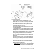
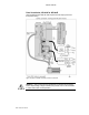
Control Power – You must install varistors or other voltage surge limiting
devices in order to meet the requirements of EN61000-4-5. Level 3
Voltage Surge (1000V line-to-line, 2000V line-to-earth) protection can
be achieved by placing a Littelfuse V275LA20C, or an equivalent
varistors from line-to-line and from line-to-earth before the mains filter as
shown in Figure 54 Typical LVD/EMC Installation, AR-20xE & AR-30xE
on pag
e 198.
Mains M
otor Power – The three-phase AC power Aries drives (models
AR-20xE and AR-30xE) are designed to meet Level 3 Voltage Surge
(1000V line-to-line, 2000V line-to-earth) without the need for external
voltage surge limiting devices. If a higher level of mains surge immunity
is required, external voltage sure limiting devices, such as varistors, can
be installed before the mains filter. Figure 54 Typical LVD/EMC
Installation, AR-2
0xE & AR-30xE on page 198 illustrat
es this installation.
Note: Intersil, General Electric, and Littelfuse manufacture equivalent
varistors.
• Use an EMC-ready motor
or a motor that has demonstrated
acceptable EMC performance.
Motors with shielded cabling or pipe thread style cabling options allow
the easiest integration into machines required to bear the CE mark for
EMC.
Note: Motors may bear the CE mark. This mark indicates the motor
meets the requirements of construction and safety—not EMC
compliance.
• Use shielded cabling with braided and bonded headshells
.
Parker EMC cabling—requires no additional cable preparation.
All motor connections must be made using a high quality braided-screen
cable. Cables using a metalized plastic bandage for an earth screen are
unsuitable and in fact provide very little screening. Care must be taken
when terminating the cable screen, the screen itself is comparatively
fragile; bending it round a tight radius can seriously affect the screening
performance. The selected cable must have a temperature rating which
is adequate for the expected operating temperature of the motor case.
All cables must maintain high integrity 360 degree shielding. Parker CE
cables are fully shielded and provide the required screening. When you
install limit switches and other inputs/outputs, you must observe these
noise immunity procedures and practices.
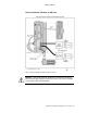
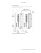
• Route cables as shown in
Figure 53 Typical LVD/EMC Installation,
AR-02xx to AR-13xx on page
197 and Figure 54 Typical LVD/EMC
Installation, AR-20xE & AR-30xE on page
198.
Route high power cables (motor and mains) at right angles to low power
cables (communications and inputs/outputs). Never route high and low
power cables parallel to each other.
Mount filters close to the drive and keep the supply wiring as short as
practical. Attempt to layout the wiring in a way that minimizes cross
coupling between filtered and non-filtered conductors. This means
avoiding running wires from the output of a filter close to those
connected to its input. Where you wish to minimize the cross coupling
between wires avoid running them side-by-side one another, if they