Automation Ethernet Networking for 6K and Gem6K Effective: February 11, 2002
User Information WARNING ! ! 6K and Gem6K Series products are used to control electrical and mechanical components of motion control systems. You should test your motion system for safety under all potential conditions. Failure to do so can result in damage to equipment and/or serious injury to personnel.
Ethernet Networking User Instruction Material Contents Ethernet Networking ......................................................................................................1 Overview ........................................................................................................1 Networking Guidelines...........................................................................................3 Configuring the 6K for Ethernet Communication ..................................................
Ethernet Networking Overview The 6K is equipped for Ethernet communication. It includes 10Base-T (10Mbps twisted pair); TCP/IP protocol. RJ-45 connector. Default IP address is 192.168.10.30. You have these options for networking the 6K over Ethernet: Setup Wizard Available The Motion Planner Wizard Editor provides a setup wizard, called “Network”, to help you establish 6K Client/Server communication (up to six servers). • 6K as a client.
• 6K as a server. The 6K waits for a PC to establish a connection with it and then provides information on a continual or requested basis. The PC communicates with the 6K using the COM6SRVR Communications Server, which is also what Motion Planner uses to communicate with the 6K (for details, refer to the COM6SRVR Communications Server Programmer’s Reference). The 6K does not support simultaneous connections with multiple clients (PCs). EXAMPLE — Closed Network: Switch or Hub Switch or Hub (255.255.255.
Setup Wizard Available The Motion Planner Wizard Editor provides a setup wizard, called “Network”, to help you establish 6K peer-to-peer communication. • Peer-to-peer network with other 6K or Gem6K units. The 6K may be connected to other 6K devices (6K Controllers or Gem6K drive/controllers) via Ethernet. Up to eight 6K devices may be networked in this manner. This type of connection uses UDP broadcasting and is not a client/server relationship.
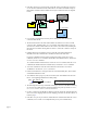
• If the 6K is placed on an open network, put the 6K and any associated server devices on one side of an Ethernet network switch with its own subnet and install a bridge to filter traffic, such that broadcast traffic does not pass in either direction (see diagram below). Ethernet Switch Ethernet Switch (255.255.255.0) out (255.255.0.0) out Bridge 6K Device 2 Client IP = 192.168.10.30 Server IP = 192.168.10.80 IP = 172.20.44.180 Ethernet Card Device 1 Server IP = 192.168.10.
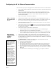
Configuring the 6K for Ethernet Communication There are three major steps in setting up Ethernet communication between a PC and controller: • • • Step 1— Preparing the Controller over RS-232 Step 2—Setting TCP/IP Properties and Static Mapping Changing the 6K’s IP Address or Subnet Mask The factory default 6K IP address is 192.168.10.30; the default mask is 255.255.255.0.
If you are using Windows NT, select the “Protocols” tab. Make sure this number is different from the one in the 6K’s IP address. If the 6K’s default IP address is unchanged (192.168.10.30), then select a number other than 30. NOTE If you are using a computer (Ethernet card) that is normally connected to a network, you should write down the existing IP Address and Subnet Mask values, so that you may restore them later. 4.
c. At the DOS prompt, type the arp –s command (see example below) and press ENTER. arp –s 192.168.10.30 0-90-55-0-0-1 192.168.10.31 6K’s IP Address (from TNT report) 6K’s Ethernet Address (from TNT report) Spaces (press the space bar) IP Address of Ethernet Card d. To verify the mapped addresses, type the arp –a command and press ENTER.
Networking with Other 6K or Gem6K Products (Peer-to-Peer) You can communicate information between 6Ks and Gem6Ks over Ethernet. This feature uses UDP broadcasting over the subnet to transfer data, so no client/server connection is needed. Up to 8 different 6K or Gem6K devices can share information, with each device having access to shared data from the 7 other devices. Each device can broadcast 8 pieces of information using “shared output” variables (VARSHO1 through VARSHO8).
NTRATE50 ; input 1 on I/O brick 1 ; Set the broadcasting rate to 50 milliseconds Third 6K or Gem6K: NTRATE50 ; Set the broadcasting rate to 50 milliseconds ; This third unit will receive data only. Therefore, it does not require ; a unit ID number or VARSHO data assignment Program Interaction Each Unit can read the broadcast variables of each other unit with the nVARSHIi command.
NTIO command to specify the type of module in that position. n \ m NTIO Network Server # Range: 1-6 Module Type. Options are: 1 = Digital/Discrete Inputs 2 = Digital/Discrete Outputs 3 = Analog Inputs 4 = Analog Outputs Module # on Server “n” Range: 0-7 For example, if there is a digital input module in slot 0, then the command would be 3\0NTIO1. If there is an Analog Input module in slot 7, then the command would be 3\7NTIO3. 7. Example Set the polling rate with the NTPOLL command.
Output #1 Output #2 Output #3 Output #4 n \ m OUT b b b b Network Server # Range: 1-6 Module # on Server “n” Range: 0-7 Options for “b” are: 1 = Turn on 0 = Turn off x = Don’t Change For example (Server #3), to turn on outputs #1 and #4 and leave outputs #2 and #3 unchanged on module #2, type 3\2OUT1XX1. To turn off only output #4, type 3\2OUT.4-0. • To set an analog output voltage, type n\mANO.
Example 6NTIP3,172,34,54,150 6NTCONN1 Program Interaction Example ; Identify a DVT camera as Server #6, located at ; IP address 172.34.54.150. ; Attempt the connection to Server #6 Once a connection has been established, you can write trigger commands to the camera using the NTWRIT command.
n NTMPRI i, i, i, i Network Server # Range: 1-6 # of Allen-Bradley data file # of first element in AB data file (beginning of range) # of elements in range # of first integer variable (VARI) in 6K (beginning of range, max value is 225) EXAMPLE: IF: • Allen-Bradley PLC is server #5 • The PLC’s integer data file 9 has 30 elements. Use data elements 15-29 (15 elements total) for integer data that is to be shared with the 6K.
Program Interaction After the connection is established, mapping has been set up, and polling enabled, the 6K starts exchanging data automatically with the PLC. Here is how to: • Write a binary variable to the PLC: Write a value to one of the VARB variables in the NTMPWB mapping. The new data is written to the binary file during the next poll. • Write an integer variable to the PLC: Write a value to one of the VARI variables in the NTMPWI mapping.
Error Conditions Error Messages page 15 The 6K will transmit error message to alert you of certain error conditions. Following are the error messages related to Ethernet networking. Error Response Possible Cause CONNECTION COULD NOT BE CLOSED OR ALREADY CLOSED Tried to close the network server connection (nNTCONNØ) when the connection was already closed. CONNECTION COULD NOT BE OPENED Tried NTCONN1 and failed. Problem could be invalid IP address or it refused a connection.
Error Handling Error Response Possible Cause NTSELP ALREADY ENABLED ON THIS TASK NTSELP, which enables program selection via OPTO22 inputs, has already been enabled (if multitasking, it has been enabled for this specific Task). OPTION CARD CAN NOT BE USED WITH ETHERNET - SEE NTFEN Tried to enable the internal Fieldbus Option card for PROFIBUS or DeviceNet communication (6Kn-PB and 6KnDN products only) with the OPTEN1 command.
Command Descriptions NTCONN Type: Syntax: Units: Range: Default: Response: See Also: Network Connect Network NTCONN n = network server # b = Enable bit n = 1-6 b = 0 (disconnect) or 1 (connect) n = 1 b = 0 1NTCONN: *1NTCONN0 ER, NTIP, [ NTS ], TER, TERF, TNTS, TNTSF Product 6K Rev 5.3 The NTCONN command attempts the connection to the server (the server # is assigned with the NTIP command).
NTID Network Sharing Unit ID for Peer-to-Peer Communication Type: Syntax: Units: Range: Default: Response: See Also: Network NTID n/a i = 0-8 i = 0 (receive variable data only, do not send variable data) NTID *NTID2 NTRATE, VARSHI, VARSHO Product 6K Rev 5.3 The NTID command establishes the Network Unit ID for a 6K unit involved in a peer-to-peer Ethernet connection with other 6K or Gem6K products. Up to eight 6K or Gem6K products may be connected in the peer-to-peer network.
NTIO Network I/O (OPTO22) Configuration Type: Syntax: Units: Range: Default: Response: See Also: Network \NTIO n = network server # m = OPTO22 I/O module # i = I/O module type identifier n = 1-6 m = 0-7 i = 1 (digital inputs), 2 (digital outputs), 3 (analog inputs), or 4 (analog outputs) 0\0NTIO0 2\3NTIO: *2\3NTIO2 \ANI, [ \ANI ], \ANO, [ \ANO ], \IN, NTCONN, NTIP, \OUT, [ \OUT ], \TIO Product 6K Rev 5.
; the OPTO22 I/O handling commands: \ANI, [ \ANI ], \ANO, [ \ANO ], ; \IN, \OUT, [ \OUT ], \TANI, \TANO, \TIN, \TIO, \TOUT page 20
NTIP Network IP Address Type: Syntax: Units: Range: Default: Response: See Also: Network NTIP,,,, n = network server # 1st i = Server type 2nd i = IP address octet1 3rd i = IP address octet2 4th i = IP address octet3 5th i = IP address octet4 n = 1-6 1st i = 1-3 (1 = Allen-Bradley PLC, 2 = OPTO22, 3 = DVT camera) 2nd i through 5th i = 0-255. n = 0 1st i = 1 2nd i through 5th i = 0 NTIP: *1NTIP1,172,54,125,34 *2NTIP1,172,54,125,67 *3NTIP ... (shows config.
NTMPRB Type: Syntax: Units: Range: Default: Response: See Also: Network Map Binary Variables for Reading from PLC Network NTMPRB,,, n = network server # 1st i = Allen Bradley data file # 2nd i = # of the 1st element in data file (beginning of range) 3rd i = # of the elements to include in range 4th i = # of the 1st binary (VARB) variable in the 6K to map to n = 1-6 1st i = 0-n (n depends on size of file) 2nd i = 0-n (n depends on size of file) 3rd i = 0 or 1-50 (0 disables polling for
2NTCONN1 2NTMPRB3,15,15,35 2NTPOLL50 WAIT(VARB40=b1111111100000000) NTMPWB Type: Syntax: Units: Range: Default: Response: See Also: ; ; ; ; ; ; ; IP address 172.54.125.
Control over Polling: If you want to stop the 6K from writing binary data to the PLC, but continue to exchange NTMPRI, NTMPWI and NTMPRB data, use the NTMPWBi,i,0,i command. If you need to stop polling all mapped variables, use the nNTPOLL0 command. Example: 2NTIP1,172,54,125,34 ; ; ; ; ; ; ; ; 2NTCONN1 2NTMPWB3,0,15,20 2NTPOLL50 VARB25 = b1111000011110000 NTMPRI Type: Syntax: Units: Range: Default: Response: See Also: Identify network server #2 as an Allen-Bradley PLC at IP address 172.54.125.
Potential Error Conditions: • You are not allowed to map the same 6K VARI variables for read and write functions. Nor are you allowed to map the same 6K VARI variables to another PLC. If you attempt either of these conditions, the 6K will not accept the NTMPRI command and will transmit the error message “VARIABLE MAPPING CONFLICT…”.
3. Map a range of integer elements in the AB PLC to a range of integer (VARI) variables in the 6K (NTMPWI command). 4. Start polling the AB device at a specific polling interval (NTPOLL command). This updates integer data elements in the AB PLC with the data from the mapped VARI variables in the 6K. NOTE: The VARI variables in the 6K are 32 bit values, but the integers in the AB PLC are 16 bit values. Therefore, the range for the VARI variables must be kept in the range –32767 to +32767.
The NTPOLL command is not saved in the 6K’s non-volatile memory. If you wish the 6K to re-establish the NTPOLL polling rate when you cycle power or issue a RESET command, put the NTPOLL command in the startup program assigned with the STARTP command. Example: 2NTIP1,172,54,125,34 2NTCONN1 2NTMPRI20,5,2,128 2NTPOLL50 NTRATE Type: Syntax: Units: Range: Default: Response: See Also: ; ; ; ; ; ; Identify network server #2 as an Allen-Bradley PLC at IP address 172.54.125.
[ NTS ] Type: Syntax: Units: Range: Default: Response: See Also: Network Status Network; Assignment/Comparison nTNTS<.i> n = server # i = bit number of status register (see table below) n = 1-6 i = 1-8 n/a n/a NTCONN, NTIP, NTPOLL, TNTSF Product 6K Rev 5.3 Use the NTS operand to assign the Network Status bits to a binary variable, or to make a comparison against a binary or hexadecimal value. Syntax: VARBx=nNTS where “n” is the network server number (e.g., VARB16=2NTS).
3. Start polling the PLC for integer data (NTPOLL). When the 6K polls the PLC, it will read the value of the mapped Element into the associated 6K integer variable (VARI). 4. Use the NTSELP command to enable the Network Program Select mode and identify the 6K integer variable (VARI) to supply the program selection number.
2NTIP3,172,54,125,34 2NTCONN1 2NTWRIT"P134" TNTS Type: Syntax: Units: Range: Default: Response: See Also: ; Network server #2 a DVT camera at IP address 172.54.125.34 ; Attempt connection to the DVT camera ; Write the string "P134" to the DVT camera Transfer Network Status Network TNTS<.
*Connection Open *Server Connection Error *In Polling Mode *Polling Timeout Error * *Reserved *Reserved *Reserved *Reserved VARSHI Type: Syntax: Units: Range: Default: Response: See Also: YES NO YES NO NO NO NO NO NO NO NO NO NO NO NO NO NO NO NO NO NO NO NO NO NO NO NO NO NO NO NO NO NO NO NO NO NO NO NO NO NO NO NO NO NO NO NO NO Shared Input Variable for Peer-to-Peer Data Exchange Product 6K Variable; Network VARSHI (see diagram below for assignment syntax) n = unit number in the
;**** This code is executed on unit #2: ************************** NTID2 ; Set unit ID to 2 NTRATE100 ; Set the sharing rate to 100ms and enable this unit VAR1=1VARSHI1 ; Load the value of unit #1's first shared data (1PE) into VAR1 WRITE"AXIS 1 AT POSITION" ; Report axis 1's current position (the value of VAR1) WRVAR1 VAR2=8PCEA-3VARSHI2 ; Calculate offset position: Subtract synch unit #3's ; VARSHO2 (4PCEA) from the captured encoder position ; of axis #8 (8PCEA).
Example: This example uses peer-to-peer communication with three 6K8 products.
[ \ANI ] Type: Syntax: Units: Range: Default: Response: See Also: Network Analog Input Voltage Status Product 6K Network; Assignment or Comparison n\mANI.i (see example below) n = network server # m = module # i = analog input # on module “m” n = 1-6 m = 0-7 j = 1-2 n/a n/a NTIO, \TANI, \TIO, VAR Rev 5.3 Use the \ANI operand to assign the voltage level of an OPTO22 analog input to a real variable (VAR), or to make a comparison against another value. Syntax: VARx=n\mANI.
\ANO Type: Syntax: Units: Range: Default: Response: See Also: Network Analog Output Product 6K Network n\mANO.i=r n = network server # m = module # i = analog output # on module “m” r = voltage value (VDC) n = 1-6 m = 0-7 i = 1-2 r = -10.00 to +10.00 n/a n/a [ \ANO ], NTIO, \TANO, \TIO Rev 5.3 Use the \ANO command to set the voltage of an OPTO22 analog output. The maximum output range can be set from – 10.00 VDC to +10.00 VDC.
[ \ANO ] Type: Syntax: Units: Range: Default: Response: See Also: Network Analog Output Status Product 6K Network; Assignment or Comparison n\mANO.i (see example below) n = network server # m = module # i = analog output # on module “m” n = 1-6 m = 0-7 j = 1-2 n/a n/a \ANO, NTIO, \TANI, \TIO, VAR Rev 5.3 Use the \ANO operand to assign the voltage level of an OPTO22 analog output to a real variable (VAR), or to make a comparison against another value.
[ \IN ] Type: Syntax: Units: Range: Default: Response: See Also: Network Digital Input Status Network; Assignment or Comparison n\mIN<=Bbbbb> (see example below) n\iIN.i (see example below) n = network server # m = module # i = digital input # on module “m” (for bit-select operation) n = 1-6 m = 0-7 j = 1-4 n/a n/a NTIO, \TIN, \TIO, VARB Product 6K Rev 5.
\OUT Type: Syntax: Units: Range: Default: Response: See Also: Network Digital Output Product 6K Network n\mOUT n\mOUT.
[ \OUT ] Type: Syntax: Units: Range: Default: Response: See Also: Network Digital Output Status Network; Assignment or Comparison n\mOUT<=Bbbbb> (see example below) n\iOUT.i (see example below) n = network server # m = module # i = digital output # on module “m” (for bit-select operation) n = 1-6 m = 0-7 j = 1-4 n/a n/a NTIO, \OUT, \TOUT, \TIO, VARB Product 6K Rev 5.
\TANI Type: Syntax: Units: Range: Default: Response: See Also: Transfer Network Analog Input Status Network; Transfer n\mTANI<.i> n = network server # m = module # i = analog input # on module “m” (for bit-select operation) (The response represents volts DC.) n = 1-6 m = 0-7 i = 1-2 n/a 1\1TANI: *2.42,3.32 1\1TANI.2: *3.32 [ \ANI ], NTIO, \TIO Product 6K Rev 5.3 The \TANI command returns the voltage present at one of the network analog inputs.
\TANO Type: Syntax: Units: Range: Default: Response: See Also: Transfer Network Analog Output Status Network; Transfer n\mTANO<.i> n = network server # m = module # i = analog output # on module “m” (for bit-select operation) (The response represents volts DC.) n = 1-6 m = 0-7 i = 1-2 n/a 1\1TANO: *2.42,3.32 1\1TANO.2: *3.32 \ANO, [ \ANO ], NTIO, \TIO Product 6K Rev 5.
\TIN Transfer Network Digital Input Status Type: Syntax: Units: Range: Default: Response: See Also: Product 6K Network; Transfer n\mTIN<.i> n = network server # m = module # i = digital input # on module “m” (for bit-select operation) n = 1-6 m = 0-7 i = 1-4 n/a 1\1TIN: *1100 1\1TIN.2: *1 [ \IN ], NTIO, \TIO Rev 5.3 The \TIN command returns the current status (active/on or inactive/off) of the network digital inputs. Each module of digital inputs has its own unique \TIN response.
* * * * \TOUT Type: Syntax: Units: Range: Default: Response: See Also: 1 2 4 7 DIGITAL OUTPUTS ANALOG OUTPUTS DIGITAL INPUTS ANALOG INPUTS 0001 +10.000, -4.456 1110 +6.753, +0.000 Transfer Network Digital Output Status Network; Transfer n\mTOUT<.i> n = network server # m = module # i = digital output # on module “m” (for bit-select operation) n = 1-6 m = 0-7 i = 1-4 n/a 1\1TOUT: *1100 1\1TOUT.2: *1 [ \OUT ], NTIO, \TIO Product 6K Rev 5.