PowerStation PA Series User Guide May 2008 Parker Electromechanical 50 W.
Copyright and Trademark Notice Copyright © 2008 by Parker Electromechanical. All rights reserved. No part of this publication may be reproduced, transmitted, transcribed, stored in a retrieval system, in any form or by any means, mechanical, photocopying, recording or otherwise, without the prior written consent of Parker Electromechanical.
Table of Contents 1 Introduction . . . . . . . . . . . . . . . . . . . . . . . . . . . . . . . . . . . . . . . . . . . . . . . . . . . . . . . Using this Manual . . . . . . . . . . . . . . . . . . . Hardware Versions . . . . . . . . . . . . . . . . . . Downloading Applications and Projects Documentation Library . . . . . . . . . . . . . . . Documentation Standards . . . . . . . . . . . . . Text Conventions . . . . . . . . . . . . . . . ISO Symbols . . . . . . . . . . . . . . . . . .
Connecting a PS/2 Mouse on 5”, 6”, 8” and 10” Units Connecting a USB Mouse on 15” Units. . . . . . . . . . . Connecting to a Serial Printer . . . . . . . . . . . . . . . . . . . . . To Adjust the Mode Settings . . . . . . . . . . . . . . . . . To Print to a Port Configured for Downloading . . . . . Ethernet Port . . . . . . . . . . . . . . . . . . . . . . . . . . . . . . . . Configuring the Ethernet Interface . . . . . . . . . . . . . CompactFlash . . . . . . . . . . . . . . . . . . . . . . . . . . . . . .
B System Configuration Files . . . . . . . . . . . . . . . . . . . . . . . . . . . . . . . . . . . . . . . . . . . . B-1 System Configuration Files. . . . . . . . . . . . . . . . . . . . . . . . . . . . . . . . . . . . . . . . . . . . B-2 Config.sys File . . . . . . . . . . . . . . . . . . . . . . . . . . . . . . . . . . . . . . . . . . . . . . . . B-2 Autoexec.bat File . . . . . . . . . . . . . . . . . . . . . . . . . . . . . . . . . . . . . . . . . . . . . .
1 INTRODUCTION Thank you for purchasing a PA PowerStation. The PA PowerStation is a rugged, compact PC that is designed to be used as an industrial operator interface. The PA PowerStation is available in five display configurations: 5”, 6”, 8”, 10”, and 15”. It has an all-in-one PC board with a Serial and Ethernet port. The PA PowerStation’s PC architecture allows you to run Parker’s Interact HMI software product. Important:You must upgrade to Interact version 6.
Chapter 1: Introduction Hardware Versions Appendix B - System Configuration Files: This section includes a complete listing of the Config.sys and Autoexec.bat files.
Chapter 1: Introduction Documentation Library Documentation Library The documentation set for this product contains: Release Notes - Release notes are provided whenever there is important information about the PowerStation that does not appear in this manual. Be sure to read any available release notes before installing or operating the unit. PA PowerStation User Guide - This document contains all the information you need to configure, install and use the PowerStation.
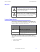
Chapter 1: Introduction Customer Support Services ISO Symbols Symbol Meaning This symbol is the International Standards Organization (ISO) symbol for Caution (ISO 3864 No. B.3.1). This symbol denotes information that could affect operation of the PowerStation if the information is not properly followed. This symbol is the ISO symbol for Caution - risk of electrical shock (ISO 3864 No. B.3.6).
Chapter 1: Introduction Customer Support Services Product Technical Support The Product Technical Support department welcomes any questions that might arise as you develop or run your applications. We offer complimentary support for all customers, including end users, original equipment manufacturers (OEM), system integrators or distributors. If you have a question about the PA PowerStation, be sure to complete the following steps: • Check any release notes that shipped with the unit.
Chapter 1: Introduction Getting Started Getting Started Now that you have opened the PA PowerStation, you are ready to unpack the unit, install it in a permanent location, and develop an application for it. Follow the steps below to get started. 1 Unpack the PowerStation and verify that you have received all of the components you ordered. 2 Install the PowerStation in a permanent location. See Chapter 2, Installing the PowerStation, for complete installation instructions.
INSTALLING THE POWERSTATION 2 Once you have unpacked the PA PowerStation and verified that you have received all of the components you ordered, you are ready to install the PowerStation in a permanent location. This chapter covers the following topics: • • • Selecting a Location Preparing for Installation Installing the PA PowerStation Selecting a Location The first step when installing the PA PowerStation is to select an appropriate location for the unit.
Chapter 2: Installing the PowerStation Selecting a Location Environmental Guidelines The environment is the area where the PA PowerStation will be located. In general, you should select a place that limits the unit’s exposure to adverse conditions such as dust, oil, moisture, and corrosive vapors. Touchscreen Considerations The PA PowerStation’s touchscreen is designed to meet the NEMA 4/4X rating. However, it is only rated NEMA 4/4X when properly mounted in a NEMA 4/4X enclosure.
Chapter 2: Installing the PowerStation Selecting a Location PA PowerStation’s have been tested for use in 50oC ambient, still air locations. This means that when installed, the ambient air surrounding the backside of the PowerStation is not expected to exceed 50oC. An example of this type of installation would be a PowerStation mounted in a small, sealed industrial enclosure.
Chapter 2: Installing the PowerStation Selecting a Location Enclosure Guidelines Select an enclosure that is large enough to allow free airflow in and around the unit. You should allow a minimum of 2 inches between the enclosure and the top, bottom, and sides of the PA PowerStation to allow access to the cabling and CompactFlash. Also, make sure that the surface of the enclosure on which the PA PowerStation is mounted is flat and free of raised or depressed areas.
Chapter 2: Installing the PowerStation Selecting a Location Class I, Division 2 Guidelines If you purchased a Class I, Division 2-compliant PowerStation, it is suitable for use in Groups A, B, C, and D hazardous locations. You must follow these guidelines in order to maintain a safe operating environment. • When performing field wiring, always use copper wire with 60C or 60/75C insulation and a tightening torque of 7.0lbs/in (0.79 N-m).
Chapter 2: Installing the PowerStation Preparing for Installation Preparing for Installation Once you select a location for the PA PowerStation, you will need to create a cutout for the unit. If you plan to operate the PA PowerStation using AC power, and you purchased Parker’s optional AC Power Supply, you will need to prepare a location for the Power Supply also. Procedures for creating the cutout and preparing a location for the AC Power Supply are described below.
Chapter 2: Installing the PowerStation Installing the PA PowerStation Installing the PA PowerStation Once you have prepared the location for your PowerStation, you are ready to install the unit. To do so, you need to mount the PowerStation to your enclosure using screws and metal clamps in what is called a bracket assembly. The bracket assembly contains a mounting clamp with “feet” and a screw. The number of clamps depends on the PA PowerStation model.
Chapter 2: Installing the PowerStation Installing the PA PowerStation 3 Slide the feet of the mounting clip into the larger portion of the slot, then slide the clip over to properly mount the unit. 4 Tighten each of the mounting screws against the front of the enclosure. 5 For 5” and 6” units: Torque them down to 6 in/lbs. For 8” and 15” units: Torque them down to 7in/lbs. For 10” units: Tighten so that the gasket seal maintains a 50% compression of the gasket.
Chapter 2: Installing the PowerStation Installing an Optional AC Power Supply Installing an Optional AC Power Supply The PA PowerStation uses only 12 or 24 volt DC power. However, you can operate the PowerStation with AC power by using an optional AC Power Supply available from Parker. Use this section only if you intend to operate the PA PowerStation using AC power. If you plan to use DC power, refer to Installing the PA PowerStation on page 2-7.
Chapter 2: Installing the PowerStation Installing an Optional AC Power Supply Connecting the Power Supply to the Workstation Once you have mounted the power supply, you are ready to connect it to the workstation. 1 Slide the positive and negative wires into the appropriate slots on the power connector that was shipped with the workstation. See Figure 2-3.
STARTING YOUR POWERSTATION 3 This chapter discusses the following topics: • PowerStation Connectors • Starting the PA PowerStation • Using the CompactFlash Card • Using the BIOS Utility The PA PowerStation is shipped with the Documentation and Utilities CD. This CD contains all of the dimensional drawings, software, and drivers needed. If any of the software on your system becomes lost or corrupted, you can reinstall it from this distribution disk.
Chapter 3: Starting Your PowerStation PowerStation Connectors communication standards that the controller supports. Use a standard DB9 connector for communicating with this port. Note: If you are using RS-232 communications, the length of the serial cable should not exceed 50 feet (15 meters). RS-422 and RS-485 communications offer greater noise immunity than RS-232. These standards increase the maximum cable length to 4,000 feet (1,200 meters).
Chapter 3: Starting Your PowerStation PowerStation Connectors Settings and Pinouts for COM1 If you need to make a cable for communicating with COM1, Table 3-1 shows the pinouts and signal information for this port.
Chapter 3: Starting Your PowerStation PowerStation Connectors Once you make a cable for communicating with COM2, you will need to set the COM2 DIP switch settings. COM2 is set to the RS-485 protocol by default. To change COM2 to the RS232 or RS-422 protocol, you must change the COM2 DIP switch settings. The DIP switch for COM2 is located on the side of the PA PowerStation, as shown in Figure 3-1 for the 5”, 6”, 8”, and 10” units.
Chapter 3: Starting Your PowerStation PowerStation Connectors Figure 3-3: Connector Pinouts and Cable Wiring on 5”, 6”, 8” and 10” Units RS-232 RS-422 RS-485 Note: Be careful not to connect any wires to unused connector pins. Dip Switch Settings and Pinouts for COM2 on 15” Units If you need to make a cable for communicating with COM2 on a 15” unit, Table 3-3, shows the pinouts and signal information for this port.
Chapter 3: Starting Your PowerStation PowerStation Connectors Caution: Note that RTS and CTS signals are not active in RS-422 and RS485 configurations. Once you make a cable for communicating with COM2, you will need to set the COM2 DIP switch settings. COM2 is set to the RS-485 protocol by default. To change COM2 to the RS232 or RS-422 protocol, you must change the COM2 DIP switch settings. The DIP switch for COM2 is located on the side of the PA PowerStation, as shown in Figure 3-4 for the 15” unit.
Chapter 3: Starting Your PowerStation PowerStation Connectors Figure 3-6, displays the connector pinouts and cable wiring required for communicating with COM1 or COM2 using the RS-232, RS-422 or the RS485 protocol. This figure is for the 15” unit only. Figure 3-6: Connector Pinouts and Cable Wiring on 15” Units RS-232 RS-422 RS-485 Note: Be careful not to connect any wires to unused connector pins.
Chapter 3: Starting Your PowerStation PowerStation Connectors Figure 3-7: Serial Transfer Cable Diagram 1 Connect a null modem serial cable to an available serial port on your development PC. 2 Connect the other end of the cable to the serial port on the PA PowerStation. 3 Launch the MachineShop Toolbar on your development PC. 4 Select File - Open Project then select the project you wish to transfer. 5 Select Transfer from the menu bar and follow the transfer wizard steps.
Chapter 3: Starting Your PowerStation PowerStation Connectors Keyboard and Mouse The PA PowerStation’s CPU board includes a keyboard port that accepts any IBM AT-compatible keyboard, including 84-key standard keyboards and 101-key enhanced keyboards. Connecting a PS/2 Mouse on 5”, 6”, 8”, and 10” Units If you prefer to use a mouse instead of the touchscreen, Parker recommends that you only use a Microsoft PS/2-style mouse, specifically an 802.3 Microsoft-compatible mouse.
Chapter 3: Starting Your PowerStation PowerStation Connectors Figure 3-8: Serial Printer Cable Diagram Use Figure 3-8 as a reference when connecting a serial printer to the PA PowerStation. Then complete the following steps: 1 From the Windows desktop, open the Startup directory within Interact project: C:\Machshop\Projects\Interact\*Project Name*\Startup\ Important Be sure to replace the pound sign with the appropriate port number when completing the next step.
Chapter 3: Starting Your PowerStation PowerStation Connectors To Print to a Port Configured for Downloading If you plan to print to a port that is configured for downloading, you will need to reconfigure the port before you can print to it. To reconfigure the port, complete the following steps: 1 Disable downloading for that port. 2 Restart the PA PowerStation. Note Restarting the PowerStation allows MODE.COM to reset the communication settings for that port. 3 Select Settings from the Main Menu.
Chapter 3: Starting Your PowerStation PowerStation Connectors Configuring the Ethernet Interface The \NET directory of the PA PowerStation’s CompactFlash contains a configuration utility and all drivers necessary to configure the Ethernet interface on the PowerStation. These files are restored when performing a reflash of the compact flash card using the Flashback Utility. A link to the Flashback Utility is listed in the PA Drivers, Documentation, and Utilities CD included with the PA PowerStation.
Chapter 3: Starting Your PowerStation Starting the PowerStation volatile memory storage. The CF is well-suited for rugged environments where the PowerStation may vibrate or shake. Although the CF is removable, it is used as an IDE drive, which means you cannot remove it while the PowerStation is switched on. The PA PowerStation supports Type 1 or Type 2 CF cards. You should purchase at least one additional CF card to serve as a backup for your primary CF card.
Chapter 3: Starting Your PowerStation Using the CompactFlash Card Using the CompactFlash Card You can remove the CF card, update the application files on the CF card from a PC, and then reinstall the CF card in the PowerStation. Reinstalling the PowerStation Utilities The PA PowerStation is shipped with the operating system and software, which is installed on the CF card that comes with your system. Backup copies of your software are provided on the PA PowerStation CD that ships with your system.
Chapter 3: Starting Your PowerStation Using the BIOS Utility Reformating the CompactFlash Card Warning:Manually formatting a CompactFlash card in Windows NT, 2000, XP, or Vista before using Flashback could possibly make the CF card unusable. Warning:Removing the CompactFlash card: During a disk transfer procedure, do not remove the CF card before issuing a Stop or shutting down the USB port service. Otherwise the last part of the data will not transfer to the CF card.
Chapter 3: Starting Your PowerStation 3 Using the BIOS Utility The CMOS memory has lost power and the configuration information has been erased. Every computer with a motherboard includes a special chip referred to as the BIOS or ROM BIOS (Read Only Memory Basic Input/Output System). The BIOS includes instructions to interact with the computer hardware. It also includes a test which ensures that the computer meets requirements to boot up properly.
MAINTAINING THE POWERSTATION 4 The PowerStation has been designed to provide years of trouble-free operation even in the harshest environments. However, occasionally you need to perform routine maintenance on some of the PowerStation’s components.
Chapter 4: Maintaining the PowerStation Maintaining the Touchscreen Calibrating the Touchscreen The monitor’s touchscreen is calibrated before leaving Parker.
Chapter 4: Maintaining the PowerStation Maintaining the Touchscreen Model No. View Size PA-08S-1XX STN Display - Full VGA PA-08T/10T/15T-1XX TFT Display - Full VGA • If your PA Series has an STN display, continue with Contrast Adjustment Steps. • If you have a TFT display, you cannot adjust the contrast. Contrast Adjustment Steps 1 Find the contrast adjustment on the back of the PowerStation. See Figure 4-1.
Chapter 4: Maintaining the PowerStation Replacing the CompactFlash Replacing the CompactFlash At some point, you will probably need to remove the CompactFlash (CF) card from the PA PowerStation flash socket for one reason or another. To do so, complete the following steps: 1 Turn off the PA PowerStation. Caution: The PowerStation must be turned off when inserting or removing the CF card to avoid corrupting data. 2 Locate the ejector next to the CF socket similiar to that shown in Figure 4-2.
Chapter 4: Maintaining the PowerStation Performing Internal Maintenance Performing Internal Maintenance Before doing any internal maintenance, be sure to read and understand the following procedures to prevent injury to yourself and/or damage to the PowerStation.
Chapter 4: Maintaining the PowerStation Performing Internal Maintenance Removing the PowerStation from an Enclosure To remove the PowerStation from it’s enclosure, follow the steps below. Explosion Hazard! • Do not connect or disconnect cables unless the power has been switched off, or the area is known to be safe. WARNING! 1 Turn off the power to the unit.
Chapter 4: Maintaining the PowerStation 4 Performing Internal Maintenance Lift the backshell off of the PowerStation to expose the board. You are now ready to perform any internal maintenance necessary. Closing the PowerStation 1 Replace the backshell on the PowerStation. 2 Remount the PowerStation in the enclosure, refer to Installing the PA PowerStation on page 2-7.
Chapter 4: Maintaining the PowerStation Performing Internal Maintenance Replacing the Fuse The PA PowerStation has a protective fuse that you can replace by opening up the back cover. An ohm meter is required to see whether the fuse is open or closed. The required fuse is listed below. • Use a Littlefuse Nano SMF Slow Blow Type fuse. The part number is R452 002. Caution: Using a fuse that is rated differently than indicated, can cause damage or fire to occur.
Chapter 4: Maintaining the PowerStation Optional Components Optional Components Parker has an optional component that you may want to purchase for the PA PowerStation —an AC Power Supply. AC Power Supply The PA PowerStation uses DC power to save space and limit the amount of heat generated by the unit. However, if you require the PowerStation to use AC power, you can purchase an AC Power Supply, P1X-PWRAC, that includes an AC Power Supply and a power cord.
Chapter 4: Maintaining the PowerStation Resolving Problems Resolving Problems This section provides some basic troubleshooting steps to help you indentify and correct problems you may have with the PA PowerStation. Each problem is described and followed with one or more possible solutions. Begin with the first solution and continue until you have solved the problem or tried all of the solutions.
Chapter 4: Maintaining the PowerStation Resolving Problems Resolving Problems when Starting Up Some of the most common problems that users encounter with PCs occur when they start up their systems. This section describes some problems that may occur in the PA PowerStation during startup and solutions for these problems. The LED Power indicator on the back of the unit does not light 1 Check to see whether the power switch is in the On position, and the PA PowerStation is operating correctly. a.
Chapter 4: Maintaining the PowerStation Resolving Problems 1 Press Exit on the MachineShop Shell menu. 2 Run ROM-DOS Edit by typing NED and then the file name that you want to edit. 3 You may also use the Flashback Utility to reformat the CF card with the default PA PowerStation files. Important: You cannot load the touchscreen driver and a serial mouse driver such as MOUSE.COM simultaneously. The PA PowerStation will only load the driver that is specified first in the AUTOEXEC.BAT file.
Chapter 4: Maintaining the PowerStation 3 Resolving Problems If all of the above remedies do not work, you may need to replace the touchscreen. Replacement Touchscreen kits are available through Parker. Resolving Problems after Start Up This section describes problems that may occur after startup and details the solutions to these problems.
Chapter 4: Maintaining the PowerStation Accessing the PowerStation Utilities 2 If you are using a PS/2 style keyboard, the keyboard should be plugged into the keyboard port. 3 If you are using an AT style keyboard, make sure the Y cable is attached to the keyboard port. 4 Try using a new Y adapter cable. 5 Try using a new keyboard. A USB keyboard or mouse doesn’t work (15” only) 1 The keyboard or mouse is defective. 2 Try a different brand.
Chapter 4: Maintaining the PowerStation Accessing the PowerStation Utilities Component Description CompactFlash (CF) card If you need additional storage capacity, you can purchase additional Compact Flash cards from Parker. You should purchase at least one additional compact flash card to serve as a backup for your primary CF. See page 4-4, for instructions on how to replace CF cards. DRAM If you need to upgrade or replace the DRAM, Parker carries replacement DRAM (DDR DIMM).
POWERSTATION SPECIFICATIONS A This appendix outlines important specifications for the PowerStation. It is a good idea to familiarize yourself with the specifications before operating your unit.
Appendix A : PowerStation Specifications Physical Specifications Physical Specifications Physical specifications include the PowerStation’s CPU, memory specifications, display types, storage capacity, and other physical characteristics. These specifications are shown in Table A-1, below. Table A-1: Physical Specifications Category PA05/PA06/PA08/PA10 Units PA15 Units Operating System ROM-DOS 6.11 ROM-DOS 6.
Appendix A : PowerStation Specifications Display Specifications Display Specifications Display specifications include the type of monitor, size, resolution, and other display properties. These specifications are shown in the following tables. There is one table for each display size: 5”, 6”, 8”, 10”, and 15”. Table A-2: PA05S Display Specifications Property PA05S Description Type Passive Color STN Display Diagonal Size 4.
Appendix A : PowerStation Specifications Display Specifications Property PA08S Description PA08T Description Brightness 120 NITS 285 NITS Bulb Life 40,000 hours 20,000 hours Adjustments External Rear Contrast n/a Left/Right 50o/50o 65o/65o Up/Down 30o/50o 65o/55o Viewing Angle Table A-5: PA10T Display Specifications Property PA10T Description Type Active Color TFT Display Diagonal Size 10.
Appendix A : PowerStation Specifications Environmental Specifications Environmental Specifications Even though the PA PowerStation is built to withstand harsh environments, limit the PowerStation’s exposure to adverse conditions such as dust, oil, moisture, and corrosive vapors to minimize maintenance and repair costs. Remember that the temperature within a protective enclosure is generally higher than the external temperature.
Appendix A : PowerStation Specifications Electrical Specifications Electrical Specifications The PA PowerStation’s power supply automatically detects the input voltage level and adjusts accordingly. However, always use reliable sources of power, and isolate all communication cables from AC power lines to enhance noise immunity. If possible, locate the PA PowerStation away from machinery that produces intense electrical noise (arc welders, etc.).
Appendix A : PowerStation Specifications Testing Specifications Testing Specifications The PA PowerStation conforms to the testing specifications listed below. Table A-9, shows the European community immunity and emission standards for electronic equipment: EN61000-6-2 (2001) and EN55011 (A2:2002).
Appendix A : PowerStation Specifications Faceplate Chemical Resistance Faceplate Chemical Resistance The touchscreen of the PA PowerStation is resistant to the chemicals listed in Table A-11.
SYSTEM CONFIGURATION FILES B Appendix B specifies the contents of two configuration files, CONFIG.CTC and AUTOEXEC.CTC. Use this information to modify or correct the files CONFIG.SYS and AUTOEXEC.BAT on the PA PowerStation.
Appendix B : System Configuration Files System Configuration Files System Configuration Files Parker includes backup copies of the CONFIG.SYS file and AUTOEXEC.BAT file in the \CTCTEMP directory on your PowerStation’s Compact Flash disk and on the PowerStation Start disk. These files are called CONFIG.CTC and AUTOEXEC.CTC. CONFIG.SYS File SHELL=C:\COMMAND.COM /E:1024 /P FILES=30 BUFFERS=30 STACKS=9,256 DEVICE=C:\DOS\HIMEM.
Appendix B : System Configuration Files System Configuration Files Command Line Parameters Description LH C:\CTC\MOUSE If a mouse is connected, installs the mouse and creates a new MOUSE.INI file. SET TOUCH_PATH=C: \HAMMOUSE CALL %TOUCH_PATH%\TS.BAT Initializes the touchscreen drivers. SET INTERACT=C:\INTERACT Sets the Interact path. SET INTERACT_FILES=C:\INTERACT\A PPFILES Sets the application path for Interact. SET INTERACT_STARTUP=C:\STARTUP Sets up Interact startup variables.
Appendix B : System Configuration Files System Configuration Files IF ERRORLEVEL 108 GOTO ERROR REM ************************************************************** REM If an external mouse is connected, MOUSE will install successfully REM and create a new MOUSE.INI file. REM ************************************************************** CD \CTC IF EXIST C:\CTC\MOUSE.INI DEL C:\CTC\MOUSE.
Appendix B : System Configuration Files System Configuration Files ECHO.