Daedal Manual No. 100-5326-01 Rev.
MX80L Series Product Manual Important User Information WARNING FAILURE OR IMPROPER SELECTION OR IMPROPER USE OF THE PRODUCTS AND/OR SYSTEMS DESCRIBED HEREIN OR RELATED ITEMS CAN CAUSE DEATH, PERSONAL INJURY AND PROPERTY DAMAGE. This document and other information from Parker Hannifin Corporation, its subsidiaries, and authorized distributors provide product and/or systems options for further investigation by users having technical expertise.
MX80L Series Product Manual MX80L Series Product Manual Table of Contents IMPORTANT USER INFORMATION............................................................................................................................................ 2 REVISION NOTES........................................................................................................................................................................ 4 CHAPTER 1 - INTRODUCTION ..........................................................
MX80L Series Product Manual Revision Notes Revision Notes Revision 1 Original Document Revision 2 – 8/25/03 General Made numerous spelling corrections Added precision grade tables Page 9 – Modified configurable to include precision grade tables Page 13 – Modified specifications to include precision grade tables Page 25 – Modified Low ESD description to include precision grade tables Revision 3 Changed wiring block extension dimension on page 10 Page 29, 30, & 31, Changed Limits/Home from optical sensors t
MX80L Series Product Manual Chapter 1 - Introduction Chapter 1 - Introduction Product Description MX80L Positioner Although the MX80L is small in size and weight, it is large on performance and reliability. All key components are integral to the unit - residing within the body of the stage to provide a clean looking, reliable, unobstructed package. At the heart of the MX80L is an innovative non-contact linear servo motor (patent pending).
MX80L Series Product Manual Chapter 1 - Introduction Return Information Returns All returns must reference a “Return Material Authorization” (RMA) number. Please call your local authorized distributor or Daedal Customer Service Department at 800-245-6903 to obtain a “RMA” number. See Daedal Catalog #8083/USA, for additional information on returns and warranty. Repair Information Out-of-Warranty Repair Our Customer Service Department repairs Out-of-Warranty products.
MX80L Series Product Manual Chapter 1 - Introduction Specification Conditions Specifications Are Temperature Dependent Catalog specifications are obtained and measured at 20 Degrees C. Specifications at any other temperature may deviate from catalog specifications. Minimum to maximum continuous operating temperature range (with NO guarantee of any specification except motion) of a standard unit before failure is 5 - 40 degrees C.
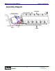
MX80L Series Product Manual Chapter 1 - Introduction Assembly Diagram CARRIAGE Anti Cage Creep Cross Roller Bearings Encoder Read Head Limit Flag Bracket +X Travel Left side of stage w.r.t.
MX80L Series Product Manual Chapter 2 – MX80L Series Table Specifications Chapter 2 – MX80L Series Table Specifications Order Number Nomenclature 9 Parker Hannifin Corporation Daedal Division Irwin, Pennsylvania
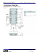
MX80L Series Product Manual Chapter 2 – MX80L Series Table Specifications Dimensional Drawings 10 Parker Hannifin Corporation Daedal Division Irwin, Pennsylvania
MX80L Series Product Manual Chapter 2 – MX80L Series Table Specifications Z-axis configuration with counter balance 25 and 50mm travel MX80L-T01 OR T02 5.6 [0.22] 16.0 [0.63] P/N 100-9822-01 QTY.(2) P/N 002-2223-01 CYLINDER ASSY. 125.0 [4.92] 13.1 [0.51] 45.0 [1.77] Z-AXIS SHOWN AT MID-TRAVEL POSITION 100mm travel MX80L-T03 MX80L-T03 5.6 [0.22] 5.6 [0.22] 16.0 [0.63] 16.0 [0.63] 002-2223-02 CYLINDER ASSY. 002-2223-02 Cylinder Ass'y. 220.0 [8.66] P/N 100-9822-02 Qty.(2) 2.1 [0.08] 2.1 [0.
MX80L Series Product Manual Chapter 2 – MX80L Series Table Specifications 150mm travel MX80L-T04 5.7 [0.22] 16.0 [0.63] P/N 002-2223-03 CYLINDER ASSY 285.0 [11.22] P/N 100-9822-02 QTY.(2) 75.0 [2.95] Z-Axis at Mid-travel 12 7.1 [0.
MX80L Series Product Manual Chapter 2 – MX80L Series Table Specifications General Table Specifications Specifications Travel 25mm 50mm 100mm 150mm Normal Load Capacity Maximum Acceleration 8 kg 8 kg 8 kg 8 kg Precision Grade Standard Grade 4G 5G 4G 5G 4G 5G 3G 4G 1100 mm/sec 1100 mm/sec 1100 mm/sec 300 mm/sec 60 mm/sec 30 mm/sec 12.0N (2.7 lbs) 4.0N (0.9 lbs) 100% 1500 mm/sec 1500 mm/sec 1500 mm/sec 300 mm/sec 60 mm/sec 30 mm/sec 12.0N (2.7 lbs) 4.0N (0.
MX80L Series Product Manual Chapter 2 – MX80L Series Table Specifications Test Methodology 2.64 6.32 -3.68 Published accuracy and repeatability specifications are subject to the testing methodology. Daedal’s methodology provides specifications over the entire table travel regardless of start or finish position. The accuracy and repeatability specifications are based on the peak to peak error measured by a laser interferometer and prism located at 38mm above the center of the table.
MX80L Series Product Manual Chapter 2 – MX80L Series Table Specifications MX80L Series Technical Data The useful life of a linear table at full catalog specifications is dependent on the forces acting upon it. These forces include both static components resulting from payload weight, and dynamic components due to acceleration/deceleration of the load. In multi-axes applications, the primary positioner at the bottom of the stack usually establishes the load limits for the combined axes.
MX80L Series Product Manual Chapter 2 – MX80L Series Table Specifications [T01] Travel Moment Life – Load Charts Life - Moment Chart 25mm travel Pitch-Yaw Loading 100000 Life [km] 10000 25 50 1000 75 100 300 250 150 200 100 0 1 2 3 4 5 6 7 8 Load [kg] Life - Moment Chart 25mm travel Roll Loading 100000 Life [km] 25 50 10000 75 100 300 1000 150 250 200 100 0 1 2 3 4 5 6 7 8 Load [kg] 16 Parker Hannifin Corporation Daedal Division Irwin, Pennsylvania
MX80L Series Product Manual Chapter 2 – MX80L Series Table Specifications [T02] Travel Moment Life – Load Charts Life-Moment Chart 50mm travel Pitch-Yaw Loading 100000 Life [km] 10000 25 50 1000 75 300 250 100 150 200 100 0 1 2 3 4 5 6 7 8 Load [kg] Life-Moment Chart 50mm travel Roll Loading 100000 25 50 10000 Life [km] 75 100 150 200 250 300 1000 100 0 1 2 3 4 5 6 7 8 Load [kg] 17 Parker Hannifin Corporation Daedal Division Irwin, Pennsylvania
MX80L Series Product Manual Chapter 2 – MX80L Series Table Specifications [T03] Travel Moment Life – Load Charts Life- Moment Chart 100mm travel Pitch-Yaw Loading 100000 25 Life [km] 10000 50 75 100 1000 150 200 300 250 100 0 1 2 3 4 Load [kg] 5 6 7 8 Life - Moment Chart 100mm travel Roll Loading 100000 25 50 75 100 Life [km] 10000 150 300 1000 200 250 100 0 1 2 3 4 Load [kg] 18 5 6 7 8 Parker Hannifin Corporation Daedal Division Irwin, Pennsylvania
MX80L Series Product Manual Chapter 2 – MX80L Series Table Specifications [T04] Travel Moment Life – Load Charts Life- Moment Chart 150mm travel Pitch-Yaw Loading 100000 25 50 75 100 Life [km] 10000 150 200 1000 300 250 100 0 1 2 3 4 5 6 7 8 Load [kg] Life- Moment Chart 150mm travel Roll Loading 100000 25 50 75 100 150 Life [km] 10000 200 250 300 1000 100 0 1 2 3 4 5 6 7 8 Load [kg] 19 Parker Hannifin Corporation Daedal Division Irwin, Pennsylvania
MX80L Series Product Manual Chapter 2 – MX80L Series Table Specifications Linear Motion Guide Bearing Life/Load Computation To predict the travel life of the MX80L cross roller bearings under a moment load use the curve with the corresponding lever arm and given load. Factor in dynamic as well as static loads. For compound loading (multiple moments) use an “effective lever arm of 2x actual lever arm.
MX80L Series Product Manual Chapter 2 – MX80L Series Table Specifications MX80L Series Technical Data Force/Speed Charts The Force/Speed Charts for the MX80L are shown for each available travel. In the maximum allowable travel range the motor force is the same for 80 and 48 VDC bus voltage. See Electrical Specifications for motor parameters. Performance based on table mounted to 200mmx150mmx20mm Aluminum plate. Curves shown include friction and viscous damping values of table.
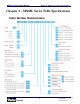
MX80L Series Product Manual Chapter 2 – MX80L Series Table Specifications [D13] 4-pole Motor Force-Speed Curve ([T03] 100 mm travel) Rated Force Speed Curve (80 & 48VDC) 30 25 Force N Peak 20 15 10 Continuous 5 0 0 400 800 1200 Speed mm/s 1600 2000 [D13] 4-pole Motor Force-Speed Curve ([T04] 150 mm travel) Rated Force Speed Curve (80 & 48VDC) 30 25 Peak Force N 20 15 10 5 Continuous 0 0 400 800 1200 Speed mm/s 22 1600 2000 Parker Hannifin Corporation Daedal Division Irwin, Pennsylvania
MX80L Series Product Manual Chapter 2 – MX80L Series Table Specifications Electrical Specifications Specifications for both the 4 pole Parameter: Stall Force Continuous [1] Stall Current Continuous [1, 4, 8] and 8 pole linear servo motors Symbol: Units: 25 & 50 mm D11 100 mm D13 150 mm D13 Fcs N 4.0 8.0 8.0 Ics(sine) Amps Peak 1.13 2.26 2.26 Stall Current Continuous [1, 7] Ics(trap) Amps DC 0.92 1.84 1.84 Stall Current Continuous [1] Ics(RMS) Amps RMS 0.8 1.6 1.
MX80L Series Product Manual Chapter 3 - How to Use the MX80 Clean Room Preparation There is no clean room ‘rating’ for motion control products just individual compatibility with class of clean rooms. The compatibility is also dependant on measurement location. A point directly below a component may have a different particle count than at a side location.
MX80L Series Product Manual Chapter 3 - How to Use the MX80 Encoder Specifications Description Input Power Output (Incremental) E2, E3, E4, E5, E8 Reference (Z Channel) Maximum Speed Specification 5 VDC +/-5% 150 to 220 mA depending on encoder resolution Square wave differential line driver (EIA RS422) 2 channels A and B in quadrature (90o) phase shift. Synchronized pulse, duration equal to one resolution bit.
MX80L Series Product Manual Chapter 3 - How to Use the MX80 Cabling and Wiring Diagrams Connector Pin Out and Extension Cable Wire Color Codes for the 5, 1, 0.5 and 0.
MX80L Series Product Manual Chapter 3 - How to Use the MX80 Chapter 3 - How to Use the MX80L Mounting Orientations The MX80L can be mounted normal, inverted, side or vertically. For vertical (z-axis) mounting the pneumatic counter balance is recommended to compensate for the effect of gravity on the carriage and the load. For all mounting orientations, the cables should be secured as to not interfere with the movement of the carriage and bearings. HORIZONTAL P/N 100-9822-02 QTY.(2) .
MX80L Series Product Manual • • • Chapter 3 - How to Use the MX80 Catalog specifications may deviate for positioners mounted to surfaces that do not meet the above conditions. If the intended mounting surface cannot meet these specifications a separate rigid mounting plate meeting these specifications should be used to mount to the main structure. If mounting conditions require that the table base is overhung, table specifications will not be met over that portion of the table.
MX80L Series Product Manual Chapter 3 - How to Use the MX80 Limit and Home sensor operation The MX80L utilizes an innovative method for setting limit and home positions. The magnetic sensors embedded in the base of the MX80L change state based on the limit “flag”. This space saving, compact design consists of three (3) parts; magnetic sensors, limit flag and limit flag bracket. The limit and home magnetic sensors are mounted to a PCB in a fixed position to the base of the unit.
MX80L Series Product Manual Chapter 3 - How to Use the MX80 Total mass = 0.46 kg (Payload mass = 250 grams + Carriage mass = 213 grams) Application Speed = 500mm/sec Available peak force at .25 m/sec = 11.8 N (See Chapter 2, Force / Speed Curve) Maximum Obtainable Deceleration Rate Thus: F = ma Æ a = F/m Æ a = 11.8N / 0.46kg Æ 25.6 m/sec2 Now, calculate the Deceleration Distance for linear deceleration: First… find the Deceleration time: Ta = Max Velocity / Deceleration Rate Ta = .50 m/sec / 25.
MX80L Series Product Manual Chapter 3 - How to Use the MX80 Step 4b: To adjust limits to reduce travel: With a razor, cut the clear protective sticker at the end of the magnet that is to be adjusted. Flatten out protective sticker at the cut, this allows a flat surface to adhere additional magnet. Place additional self adhesive magnet (supplied with positioner) at the end of the existing magnet which equals the amount of desired travel reduction.
MX80L Series Product Manual Chapter 3 - How to Use the MX80 repeatability the final homing speed must be slow. Slower final speed usually results in higher repeatability. NOTE: The “Z” channel output is only one resolution count wide. Thus the on-time may be very brief. Due to this some controllers may have difficulty reading the signal.
MX80L Series Product Manual Chapter 3 - How to Use the MX80 For multi-axis configurations special attention needs to be taken into account for the moving cables on the non-base axis. TIP: For Multi-axis Configurations. Consider using the top axis for the highest frequency move in the application. The top axis will have the least amount of weight to move and will reduce the cycles on the cables.
MX80L Series Product Manual Chapter 4 - Performance Chapter 4 - Performance Acceleration Limits Acceleration of linear servo driven tables is typically limited by three (3) factors; linear bearings, available motor force and settling time. Due to the high load bearings used in the MX80, the acceleration is only limited by the available motor force and the settling time. • Available Motor Force This is the primary factor that reduces acceleration.
MX80L Series Product Manual Chapter 4 - Performance Thermal Effects on Accuracy The MX80L uses a moving magnet linear servo motor. The magnet rails and the encoder tape are mounted to the carriage. The motor coils are mounted in the base and unless the table is mounted to an insulated surface, the heat generated in the coils should radiate out the base maintaining a low thermal delta between base and carriage. All specifications for the MX80L are taken at 20 C.
MX80L Series Product Manual Chapter 4 - Performance Causes of Temperature Increases One or more of the following conditions may affect the temperature of the MX80L carriage: • Ambient Temperature This is the air temperature that surrounds the MX80L • Application or Environment Sources These are mounting surfaces or other items which produce a thermal change that affect the temperature of the MX80L carriage (i.e.
MX80L Series Product Manual Chapter 5 - Connecting the ViX Amplifier Chapter 5 - Connecting to the ViX Amplifier The MX80L is designed to be plug and run compatible with the Parker ViX drive. The cables on the MX80L are labeled to match the labels on the ViX for ease of use and quick installation. When purchased as part of the part number, the ViX will have the motor parameters already downloaded.
MX80L Series Product Manual Appendix Chapter 6 - Maintenance and Lubrication Cross Roller Bearing Lubrication Standard Prep: • Recommended Lubricant: Mobil Vactra No. 2, oil • Lubrication Interval: 1000 hours* • Method: Lightly coat the bearing surfaces with oil. Bearings surfaces can be exposed by moving the table to the end of travel lubricating the now exposed surfaces, then moving the table to the other end of travel and lubricating the other set of surfaces.
MX80L Series Product Manual Appendix Appendix A - Internal Protection Daedal has conducted testing to determine the degree to which the positioner is protected by using a British standard called an Ingress Protection Rating (IP Rating). The MX80L has an IP 10 protection rating. Definition Reference: British standard EN 60529 : 1992 This standard describes a system of classifying degrees of protection provided by enclosures of electrical equipment.
MX80L Series Product Manual Index Index Acceleration Limits, 39 Specifications, 13 Accuracy Specifications, 13 Thermal Effects, 40, 41 Assembly Diagram, 8, 44 Hall Effect Specifications, 27 Home Sensor, 9 Adjusting, 35 Specifications, 27 ViX, 43 Horizontal Translation, 21 Bearing Life, 16 Load, 21 Lubrication, 45 Bend Radius, 36 Ingress Protection Rating, 46 Internal Protection, 46 Cabling, 9, 36, 37 Cleanroom, 25, 38, 45 Counter Balance, 37 Deceleration Distance, 33 Dimensional Drawings, 11 Drive Amp