Compumotor OEM6250 Servo Controller Installation Guide Compumotor Division Parker Hannifin Corporation p/n 88-016524-01B March 1998
User Information ! WARNING ! 6000 Series products are used to control electrical and mechanical components of motion control systems. You should test your motion system for safety under all potential conditions. Failure to do so can result in damage to equipment and/or serious injury to personnel.
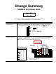
Change Summary OEM6250 Installation Guide Rev B March 1998 The following is a summary of the primary technical changes to this document. This book, p/n 88-016524-01B, supersedes 88-016524-01A. Topic De s c ript ion Error Correction: DFT Input Circuit Revision A incorrectly stated that the drive fault input (DFT pin on the DRIVE connectors) shared the same circuit design as the limit inputs and trigger inputs. DFT is not controlled by the AUX-P pullup terminal and is not affected by the R45 resistor.
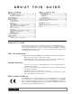
ABO U T T H I S G U I D E Chapter 1. Installation Chapter 2. Troubleshooting What You Should Have (ship kit) ........................................................... 2 Before You Begin ..................................................................................... 2 Recommended Installation Process ............................................. 2 Electrical Noise Guidelines ........................................................... 2 General Specifications .....................................
1 CHAP T E R ONE Installation IN THIS CHAPTER • • • • • • • • Product ship kit list Things to consider before you install the OEM6250 General specifications table Mounting the OEM6250 Connecting all electrical components (includes specifications) Testing the installation Tuning the OEM6250 (refer to Servo Tuner User Guide or to Appendix A) Preparing for what to do next Appendix B provides guidelines on how to install the OEM6250 in a manner most likely to minimize the OEM6250’s emissions and to maximize
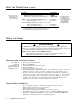
What You Should Have (ship kit) Part Name Part Number One of the following line items: OEM6250 standard product (with ship kit) .............................. OEM6250 OEM6250 product with ANI input board (with ship kit)........... OEM6250-ANI If an item is missing, call the factory (see phone numbers on inside front cover). Ship kit: This manual (OEM6250 Installation Guide) * ............. 88-016524-01 Motion Architect response card ** ...............................
General Specifications Parameter Specification Power DC input.................................................................... 5VDC ±5%, 4A minimum (current requirements depend on the type and amount of I/O used – see page 20). Status LEDs/fault detection...................................... Refer to Diagnostic LEDs on page 28 Environmental Operating Temperature .......................................... 32 to 122°F (0 to 50°C) Storage Temperature...............................................
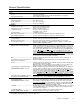
Mounting the OEM6250 NOTE: The drawing below illustrates the dimensions of the OEM6250 printed circuit board. The board is shipped from the factory attached to sheet metal which allows either flat mounting or side mounting of the OEM6250. This board will fit in a 6U rack (if you remove the PCB from the sheet metal). Max. Component Height 10.01 (254.25) 9.67 (245.62) 1.48 (37.59) 11.00 (279.40) 10.10 (256.54) 9.19 (233.43) 0.50 (12.70) 0.70 (17.78) 1.00 (25.40) 1.00 (25.
Electrical Connections Appendix B (page 47) provides guidelines on how to install the OEM6250 in a manner most likely to minimize the OEM6250’s emissions and to maximize the OEM6250’s immunity to externally generated electromagnetic interference.
Serial Communication RS-232C Connections RS-232C Daisy-Chain Connections * Unit 0 9 1 AUX 1 Tx Rx GND Pin 2 (Rx) Pin 3 (Tx) Pin 5 (GND) 9 Pin 2 (Tx) Pin 3 (Rx) Pin 7 (GND) Unit 0 1 Rx Tx GND SHLD RP240 5 Rx Tx GND 9 Unit 1 Unit 2 Rx Tx GND SHLD Rx Tx GND SHLD Daisy Chain to a Computer or Terminal 25-Pin COM Port: Rx Tx GND Tx Rx GND LIMITS Rx Tx GND SHLD 7 1 Serial Port Connection 9-Pin COM Port: Rx Tx GND SHLD Unit 1 Unit 2 Rx Tx GND SHLD Rx Tx GND SHLD Stand-Alone Daisy Chain
Motor Drivers WARNING REMOVE DC POWER FIRST before connecting or disconnecting the drive. CONNECTIONS & INTERNAL SCHEMATICS Drive Motor Maximum recommended cable length is 15 feet (4.56 m). Use 22 AWG wire. Internal Schematics Chassis Ground Solid State Relay DRIVE Connector OEM6250 DRIVE 1 DRIVE 2 SHLD COM SHTNC SHTNO DFT AGND RSVD CMD– CMD+ Closed if DRIVE¯ Open if DRIVE1 Open if DRIVE¯ Closed if DRIVE1 47 KW Analog Ground (AGND) 74HCxx 6.
PIN OUTS & SPECIFICATIONS (9-pin DRIVE Connector) Name SHLD COM SHTNC In/Out — — OUT SHTNO OUT DFT IN AGND RSVD CMD– CMD+ — — IN OUT Description and Specifications Shield—Internally connected to chassis (earth) ground. Signal common for shutdown. Not connected to any ground or other COM. Shutdown relay output to drives that require a closed contact to disable the drive. The shutdown relay is active (disabling the drive) when no power is applied to the OEM6250.
BD-E Drive BD-E Drive User I/O Connector OEM6250 DRIVE 1 15 BD-E Drive 8 V2 (pin 1) « CMD– V1 (pin 2) « CMD+ GND (pin 4) « GND RST (pin 5) « COM +15V (pin 6) « SHTNO ENCODER 1 SHLD COM SHTNC SHTNO DFT AGND RSVD CMDÐ CMD+ OEM6250 9 1 FT (pin 9) « DFT +5V A+ AÐ B+ BÐ Z+ ZÐ GND SHLD AOP (pin 10) « A– AOP (pin 11) « A+ BOP (pin 12) « B+ BOP (pin 13) « B– ZOP (pin 14) « Z+ ZOP (pin 15) « Z– NOTE: These connections will work only if BD-E jumper LK2 is set to position B (not the factory default positio
OEM670 Drive OEM6250 OEM670 Drive 1 OEM670 Drive OEM6250 14 DRIVE 1 CMD+ (pin 1) « CMD+ CMD– (pin 2) « CMD– FAULT (pin 9) « DFT SHLD COM SHTNC SHTNO DFT AGND RSVD CMDÐ CMD+ ENABLE (pin 10) « SHTNO GND (pin 11) « COM GND (pin 16) « AGND 13 25 SV Drive SV Drive SOLL1+ (X8 pin 01) SOLL1– (X8 pin 02) N (X13 pin 02) B (X13 pin 03) A (X13 pin 04) GND (X13 pin 05) N/ (X13 pin 09) B/ (X13 pin 10) A/ (X13 pin 11) +5V (X13 pin 13) ENABLE GND (X10 pin 08) +24V OUT GND (X10 pin 10) ENABLE (X10 pin 01) +24V O
ANI Analog Input (OEM6250-ANI or OPT-OEM6250-A product only) ±10V Ana og Input Source Signal Source + Ground – Internal Schematics 6 5 4 3 2 1 +15V Analog Input #1 Analog Input #2 Analog Ground N.C. N.C. N.C. (same as #1) LF412 150 KW -15V ANI Option Board Analog Ground Analog Ground ¥ Each input is a ±10V analog input with a 14-bit analog-to-digital converter. ¥ The ANI input is sampled at the servo sampling rate (see table for SSFR command).
End-of-Travel and Home Limit Inputs NOTES • CAUTION: As shipped from the factory, the limit inputs are pulled up to +5V through the R45 resistor. To use a voltage reference other than +5V, first remove R45 and then use either the on-board +5V terminal or an external power supply to power the AUX-P pull-up resistor (using both will damage the OEM6250). • Motion will not occur on an axis until you do one of the following: - Install end-of-travel (POS & NEG) limit switches.
Encoder CONNECTIONS & INTERNAL SCHEMATICS Internal Schematic ENCODER Connector Max. Cable Length is 100 feet. Use 22 AWG wire. Incremental Encoder +5VDC Red A Channel + Brown A Channel – Brown/White B Channel + Green B Channel – Green/White Z Channel + Orange Z Channel – Orange/White Ground Black Shield Shield +1.
Joystick & Analog Inputs CONNECTIONS Joystick potentiometers are 5KW with 60° of usable travel adjusted to span 0W to 1KW. * 1KW Resistors * X Axis 5KW The 1KW resistors for velocity select, axes select, joystick trigger, & joystick auxiliary are for noise suppression only. J O Y S T I C K Y Axis 5KW N.C.
Trigger Inputs TRG-A & TRG-B connected to GND Internal Schematic AUX Connector (normally-open switches). SHLD +5V OUT-P IN-P The active level (default is active low) can be changed with the INLVL command. These inputs are like the general-purpose inputs on the 50-pin header.
General-Purpose Programmable Inputs & Outputs PIN OUTS & SPECIFICATIONS 2 50 49 PROGRAMMABLE INPUT/OUTPUT 1 Pin 50-pin plug is compatible with VM24 and OPTO-22™ signal conditioning equipment.
INPUT CONNECTIONS — Connecting to electronic devices such as PLCs Electronic Device OEM6250 GND Pulled up to +5V (sourcing) The output should be able to sink at least 1mA of current. GND +5V +5VDC IN-P Out 5-24 Volts Output Input Connection Ground Ground Connection 6.8 KW Connection to a Sinking Output Device R12 (0 KW) Remove if you wish to use an external 5-24V power source.
OUTPUT CONNECTIONS (includes OUT-A & OUT-B) — for electronic devices such as PLCs Connection to a Sinking Input (active high) External Supply (up to 24VDC) Electronic Device + Connection to a Sourcing Input (active low) OEM6250 – External Supply (up to 24VDC) Electronic Device GND + – OEM6250 GND GND +5V OUT-P Input Output Connection Ground Ground Connection GND +5V +5VDC R13 (0 KW) is removed. V+ OUT-P Input Output Connection Ground Ground Connection 4.
THUMBWHEEL CONNECTIONS — for entering BCD data Connection to the Compumotor TM8 Module TM8 Thumbwheel Module + 1 2 3 4 5 6 7 8 +5 GND I5 I4 I3 I2 I1 O5 O4 O3 O2 O1 OEM6250 Programmable Input #1 Programmable Input #2 Programmable Input #3 Programmable Input #4 Programmable Input #5 Pin #49 (+5VDC) Pin #48 (GND) Programmable Output #1 Programmable Output #2 Programmable Output #3 Optional Sign Bit Connection to your own Thumbwheel Module Input #9 (sign) Input #8 MSB Input #7 Input #6 Input #5 LSB
RP240 Remote Operator Panel RP240 Back Plane RP240 SHLD Tx Rx GND +5V GND Rx Tx +5V Input Power (+5VDC ±5%, 4A minimum) Current Requirements The current requirements for the +5VDC supply depend on the type and amount of I/O used.
Lengthening I/O Cables Bear in mind that lengthening cables increases noise sensitivity. (The maximum length of cables is ultimately determined by the environment in which the equipment will be used.) If you lengthen the cables, follow the precautions below to minimize noise problems. • Use a minimum wire size of 22 AWG. • Use twisted pair shielded cables and connect the shield to a SHLD terminal on the OEM6250. Leave the other end of the shield disconnected.
Testing the Installation WARNING • This test procedure allows you to control I/O; therefore, make sure that exercising the I/O will not damage equipment or injure personnel. • The procedures below are designed to be executed with the drives not connected to the OEM6250; therefore, do not proceed until you have disconnected the drives from the OEM6250. Test Setup 1 Serial Connection RS-232C (see page 6) To communicate with the OEM6250, you will need a terminal emulation program.
Connections Test Procedure Response Format (left to right) Analog Output Signal 1. If the servo drives are connected to the OEM6250’s DRIVE connectors, disconnect them. 2. Set all the gains to zero by entering these commands: SGP¯,¯ , SGI¯,¯ , SGV¯,¯ , SGAF¯,¯ , and SGVF¯,¯ . 3. Enter the DRIVE11 command to enable the OEM6250 to send out the analog command. 4. Set the DAC output limit to 10 volts by entering the DACLIM1¯,1¯ command. 5.
Tuning the OEM6250 Before tuning the OEM6250, mount and couple the motors as required for your application. To assure optimum performance, you should tune your servo system. The goal of the tuning process is to define the gain settings, servo performance, and feedback setup (see command list below) that you can incorporate into your application program. (Typically, these commands are placed into a setup program – see examples in the Basic Operations Setup chapter of the 6000 Series Programmer’s Guide).
What’s Next? By now, you should have completed the following tasks, as instructed earlier in this chapter: 1. Review the general specifications — see page 3. 2. Mount the OEM6250 — see page 4. 3. Connect all electrical system components — see pages 5-21. EMC installation guidelines are provided in Appendix B (page 47). 4. Test the installation — see pages 22-23. 5. Mount the motor and couple the load. 6. Tune the OEM6250 (see Servo Tuner User Guide or Appendix A for instructions).
2 CHAP T E R T WO Troubleshooting IN THIS CHAPTER • Troubleshooting basics: - Reducing electrical noise - Diagnostic LEDs - Test options - Technical support • Solutions to common problems • Resolving serial communication problems • Product return procedure
Troubleshooting Basics When your system does not function properly (or as you expect it to operate), the first thing that you must do is identify and isolate the problem. When you have accomplished this, you can effectively begin to resolve the problem. The first step is to isolate each system component and ensure that each component functions properly when it is run independently. You may have to dismantle your system and put it back together piece by piece to detect the problem.
Common Problems & Solutions NOTE Some software-related causes are provided because it is sometimes difficult to identify a problem as either hardware or software related. Problem Communication (serial) not operative, or receive garbled characters. Direction is reversed. (stable servo response) Direction is reversed. (unstable servo response) Distance, velocity, and accel are incorrect as programmed. Cause 1. Improper interface connections or communication protocol. 2. Serial communication is disabled. 3.
Problem/Cause/Solution Table (continued) Problem Programmable inputs not working. Programmable outputs not working. Runaway (if encoder counts positive when turned clockwise). Torque, loss of. Trigger, home, end-oftravel, or ENBL inputs not working. Cause 1. IN-P (input pull-up) not connected to a power supply. 2. If external power supply is used, the grounds must be connected together. 3. Improper wiring. Solution 1.a.
3. Type “TREV” and press the ENTER key. (The TREV command reports the software revision.) The screen should now look like the one shown below; if not, see Problem/Remedy table below. *PARKER COMPUMOTOR OEM6250 - 2 AXIS SERVO CONTROLLER *RP240 CONNECTED >TREV *TREV92-013471-01-4.7 OEM6250 Problem Remedy (based on the possible causes) No Response • COM port not enabled for 6000 language communication. Issue the “PORT1” command and then the “DRPCHK¯” command.
Product Return Procedure 32 Step 1 Obtain the serial number and the model number of the defective unit, and secure a purchase order number to cover repair costs in the event the unit is determined by the manufacturers to be out of warranty.
Appendix A Tuning In this appendix: • Servo control terminology • Servo control techniques • Servo tuning procedures (These procedures are based on empirical techniques. If you are using Servo Tuner™, refer to the Servo Tuner User Guide for instructions.) You should tune the OEM6250 before attempting to execute any motion functions.
Servo System Terminology saturation. When saturation occurs, increasing the gains does not help improve performance since the DAC is already operating at its maximum level. This section gives you an overall understanding of the principles and the terminology used in tuning your OEM6250. Position Variable Terminology Servo Tuning Terminology The OEM6250 uses a digital control algorithm to control and maintain the position and velocity.
Servo Response Terminology Stability The first objective of tuning is to stabilize the system. The formal definition of system stability is that when a bounded input is introduced to the system, the output of the system is also bounded. What this means to a motion control system is that if the system is stable, then when the position setpoint is a finite value, the final actual position of the system is also a finite value.
Tuning-Related Commands More detailed information on each 6000 Series command can be found in the 6000 Series Software Reference. The block diagram below shows these control techniques in relation to the servo control algorithm configuration. The following table presents a condensed summary of each control’s effect on the servo system. Servo Control Algorithm Servo System Velocity Feedforward Tuning Gains: SGP .............. Sets the proportional gain in the PIV&F servo algorithm. SGI ..............
The primary function of the integral control is to overcome friction and/or gravity and to reject disturbances so that steady state position error can be minimized or eliminated. This control action is important for achieving high system accuracy. However, if you can achieve acceptable position accuracy by using only the proportional feedback (SGP), then there is no need to use the integral feedback control.
gain is needed for adequate damping, you can balance the tracking error by applying velocity feedforward control (increasing the SGVF value—discussed below). Since the feedback device’s velocity is derived by differentiating the feedback device’s position with a finite resolution, the finite word truncation effect and any fluctuation of the feedback device’s position would be highly magnified in the velocity value, and even more so when multiplied by a high velocity feedback gain.
Tuning Setup Procedure Use the following procedure to set up your servo system before completing the tuning procedures. You can perform this procedure for both axes simultaneously. Before you set up for tuning: Do not begin this procedure unless you are sure you have successfully completed these system connection, test, and test procedures provided in Chapter 1: • Connect the drive (especially the drive’s shutdown output). • Connect and test the feedback devices.
d. Use the TFB command again to observe the feedback device’s position. The value should have increased from the value observed in Step 7.b. If the position reading decreases when using a positive SOFFS setting, turn off the OEM6250 and the drive and swap the CMD+ and CMD- connections either at the OEM6250 or at the drive, whichever is more accessible (this will not work for servo drives that do not accept differential input).
VELOCITY Command Velocity Actual Velocity TIME Step 3 Proceed to the Controller Tuning Procedure section to tune the OEM6250. Controller Tuning Procedure The Controller Tuning Procedure leads you through the following steps: 1. Setup up for tuning. 2. Select the OEM6250’s servo Sampling Frequency Ratios (SSFR). 3. Set the Maximum Position Error (SMPER). 4. Optimize the Proportional (SGP) and Velocity (SGV) gains. 5. Use the Integral Feedback Gain (SGI) to reduce steady state error. 6.
Step 4 Step 5 Optimize the Proportional (SGP) and Velocity (SGV) gains (see illustration on next page for tuning Use the Integral Feedback Gain (S G I ) to reduce steady state error. (Steady state position process). error is described earlier in the Performance Measurements section on page 35.) a. Enter the following commands to create a step input profile (use a comma in the first data field when tuning axis 2—e.g.
Tuning Process Flow Diagram (using proportional and velocity gains) START Increase SGP UNTIL OR OR Decrease SGV UNTIL Increase SGV UNTIL OR Decrease SGV UNTIL OR STOP Decrease SGP UNTIL OR Increase SGV UNTIL OR Decrease SGV UNTIL Step 6 Step 7 Use the Velocity Feedforward Gain (SGVF) to reduce position error at constant speed. Use the Acceleration Feedforward Gain (SGAF) to reduce position error during acceleration. a.
Tuning Scenario This example shows how to obtain the highest possible proportional feedback (SGP) and velocity feedback (SGV) gains experimentally by using the flow diagram illustrated earlier in Step 4 of the Tuning Procedure. Step 4 As we iteratively increase SGP to 105, overshoot and chattering becomes significant (see plot). This means either the SGV gain is too low and/or the SGP is too high. Next, we should try raising the SGV gain to see if it could damp out the overshoot and chattering.
Step 8 After raising the SGV gain to 2.4, overshoot is reduced a little, but chattering reappears. This means the gains are still too high. Next, we should lower the SGV gain until chattering stops. Step 12 Now that we have determined the appropriate SGP and SGV gains, we can include them in the OEM6250’s setup program. We put the gains in the setup program because we want the OEM6250 to power up in a “ready state” for motion.
Appendix B EMC Installation Guidelines General Product Philosophy The OEM6250 was not designed originally for EMC compliance. Therefore, it will require specific measures to be taken during installation. The ultimate responsibility for ensuring that the EMC requirements are met rests with the systems builder. It is important to remember that for specific installations, the full protection requirements of the EMC Directive 89/336/EEC need to be met before the system is put into service.
cable (this allows the braid to continue to the cable connector), be careful not to damage the braid. Snap the P-clip over the exposed braid, and adjust for a tight fit. Secure the clip to the designated ground with a machine screw and lock washer. The use of brass or other inert conductive metal P-clip is recommended. Cover any exposed bare metal with petroleum jelly to resist corrosion. P-Clip Remove outer jacket only do not cut braid Figure 2.
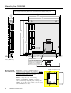
Limits Cable Drive Cable Remove paint if mounting on this surface Encoder Cable Braided-screen Cables Communications Cable User provided power from a clean DC power supply (use twisted pair cable) Triggers Cable Ground Strap (connect to TH1) Remove Paint Programmable I/O Cable I/O Flat Cable VM50 Figure 3.
I N D E X 5V power input (external supply) 20 5V power supply (internal) connections to (see page for connection item, like ENBL, Encoder, etc.) load limit 3, 20 6000user@cmotor.
F FAX number for technical support 28 feedback data 34 feedback device polarity reversal 29 feedback, e-mail address i ferrite absorbers 47 G gains definition of 34 gain sets, saving & recalling 38 tuning controller 41 drive 40 setup 39 grounding 2 EMC guidelines 47 system diagram 5 H handshaking, disabling 30 hard limits (end-of-travel) (see end-oftravel limits) HCMOS-compatible voltage levels 3 heat 3 helpful resources (publications) i home limit input connections & specs 12 testing 22 humidity 3 I I/O
servo control methods/types 36 open loop operation 39 sampling frequency 34, 41 tuning, see tuning servo sampling update rate 3 setpoint 34 settling time 35 shielding 2 EMC guidelines 47 I/O cables 21 ship kit 2 shut down in case of emergency 39 shutdown output to drive 8 sinking input device, connecting to 18 sinking output device, connecting to 15, 17 software, update from BBS 28 sourcing input device, connecting to 18 sourcing output device, connecting to 15, 17 specifications, overall list of (see also
OEM6250 2-Axis Servo Controller Automation Connections See also pages 5-23 I/O SPECIFICATIONS & INTERNAL SCHEMATICS DC Input............5VDC ±5%, 4A min. (current requirements depend on .....................the type and amount of I/O used – see page 20). Serial Com.........RS-232C 3-wire (Rx, Tx & GND on AUX connector); .....................Up to 99 units in a daisy chain. .....................9600 baud (or use AutoBaud feature – see page 6); .....................8 data bits; 1 stop bit; no parity.